- 2006 Nissan 350z Owners Manuals
- Nissan 350z Owners Manuals
- 2005 Nissan 350z Owners Manuals
- Nissan 350z Owners Manuals
- 2004 Nissan 350z Owners Manuals
- Nissan 350z Owners Manuals
- 2007 Nissan 350z Owners Manuals
- Nissan 350z Owners Manuals
- 2003 Nissan 350z Owners Manuals
- Nissan 350z Owners Manuals
- 2008 Nissan 350z Owners Manuals
- Nissan 350z Owners Manuals
- Download PDF Manual
-
Fastening the seat belts 1. Adjust the seat. 2. Slowly pull the seat belt out of the retractor and insert the tongue into the buckle until it clicks.
The retractor is designed to lock during a sudden stop or on impact. A slow pulling motion will permit the belt to move, and allow you some freedom of movement in the seat. 3. Position the lap belt portion low and snug
on the hips as shown.
During normal seat belt use by a passen- ger, the locking mode should not be acti- vated. If it is activated it may cause uncom- fortable seat belt tension.
WARNING
When fastening the seat belts, be cer- tain that seatbacks are completely se- cured in the latched position. If they are not completely secured in the right po- sition, passengers may be injured in an accident or sudden stop.
4. Pull
the shoulder belt portion toward the
retractor to take up extra slack.
The front passenger seat belt has a cinching mechanism for child restraint installation. It is referred to as the automatic locking mode. (Also remember, if you need to install a child restraint, first obtain an air bag ON/OFF switch and turn the passenger air bag OFF.) When the cinching mechanism is activated the seat belt cannot be withdrawn again until the seat belt tongue is detached from the buckle and fully retracted. For additional information, see “Child restraints” later in this section. The automatic locking mode should be used only for child restraint installation.
Seats, restraints and supplemental air bag systems 1-23
Z 02.9.13/Z33-D/V5.0 X
ward. The retractor should lock and restrict further belt movement.
If the retractor does not lock during this check or if you have any questions about belt operation, see your NISSAN dealer.
SSS0021
Unfastening the seat belts To unfasten the belt, press the button on the buckle. The seat belt will automatically retract. Checking seat belt operation Your seat belt retractors are designed to lock belt movement using two separate methods: I when the belt
is pulled quickly from the
retractor.
I when the vehicle slows down rapidly. You can check their operation as follows: I grasp the shoulder belt and pull quickly for- 1-24 Seats, restraints and supplemental air bag systems
SSS0210
Seat belt hook Hook the seat belt and its tongue qA at the belt hook when it is not in use or when opening the rear floor box lid. SEAT BELT EXTENDERS If, because of body size or driving position, it is not possible to properly fit the lap-shoulder belt and fasten it, an extender is available which is compatible with the installed seat belts. The extender adds approximately 8 inches (200 mm) of length and may be used for either the driver or passenger seating position. See your NISSAN dealer for assistance if the extender is required.
Z 02.9.13/Z33-D/V5.0 X
mended for cleaning upholstery or carpets. Then brush the webbing, wipe it with a cloth and allow it to dry in the shade. Do not allow the seat belts to retract until they are com- pletely dry.
I If dirt builds up in the shoulder belt guide of the seat belt anchors, the seat belts may retract slowly. Wipe the shoulder belt guide with a clean, dry cloth.
I Periodically check to see that the seat belt and the metal components such as flexible wires buckles, tongues, retractors, and anchors work properly. If loose parts, deterioration, cuts or other damage on the webbing is found, the entire belt assembly should be replaced.
WARNING
I Only NISSAN seat belt extenders, made by the same company which made the original equipment belts, should be used with NISSAN seat belts.
I Persons who can use the standard seat belt should not use an extender. Such unnecessary use could result in serious personal injury in the event of an accident.
I Never use seat belt extenders to in- stall child restraints. If the child re- straint is not secured properly, the child could be seriously injured in a collision or a sudden stop. (Also re- member never to use a child restraint unless an air bag ON/OFF switch has been installed and is being used properly.)
SEAT BELT MAINTENANCE I To clean the seat belt webbings, apply a mild soap solution or any solution recom-
CHILD RESTRAINTS
PRECAUTIONS ON CHILD RESTRAINTS
WARNING
The information in this section is pro- vided only for those owners who have received permission to install an air bag ON/OFF switch and the switch has been installed. See “Obtaining an air bag ON/OFF switch” earlier in this manual. Never let children 12 or under ride in this vehicle unless an air bag ON/OFF switch is installed and it is being prop- erly used.
WARNING
I Infants and small children should al- ways be placed in an appropriate child restraint while riding in the ve- hicle. Failure to use a child restraint can result in serious injury or death. I Infants and small children should never be carried on your lap. It is not
Seats, restraints and supplemental air bag systems 1-25
Z 02.9.13/Z33-D/V5.0 X
possible for even the strongest adult to resist the forces of a severe acci- dent. The child could be crushed be- tween the adult and parts of the ve- hicle. Also, do not put the same seat belt around both your child and your- self.
I Never install a child restraint in the front seat unless an air bag ON/OFF switch has been installed and the air bag has been turned OFF. An inflat- ing supplemental air bag could seri- ously injure or kill your child.
I An improperly installed child re- straint could lead to serious injury or death in an accident.
In general, child restraints are designed to be installed with the lap portion of a three-point type seat belt.
The proper restraint depends on the child’s size. Generally, infants (up to about 1 year and less than 20 lb (9 kg) should be placed in rear facing child restraints. Front facing child restraints are available for children who outgrow rear facing child restraints.
Child restraints for infants and children of various sizes are offered by several manufacturers. When selecting any child restraint, keep the following points in mind: I choose only a restraint with a label certifying that it complies with Federal Motor Vehicle Safety Standard 213 or Canadian Motor Vehicle Safety Standard 213.
I check the child restraint in your vehicle to be sure it is compatible with the vehicle’s seat and seat belt system.
I if the child restraint is compatible with your vehicle, place your child in the child restraint and check the various adjustments to be sure the child restraint is compatible with your child. Always follow all recommended proce- dures.
All US states and Canadian provinces re- quire that infants and small children be restrained in approved child restraints at all times while the vehicle is being oper- ated.
WARNING
I Improper use of a child restraint can result in increased injuries for both
1-26 Seats, restraints and supplemental air bag systems
the infant or child and other occu- pants in the vehicle.
I Follow all of the child restraint manu- facturer’s instructions for installation and use. When purchasing a child restraint, be sure to select one which will fit your child and vehicle. It may not be possible to properly install some types of child restraints in your vehicle.
I If the child restraint is not anchored properly, the risk of a child being injured in a collision or a sudden stop greatly increases.
I Adjustable seatbacks should be po- sitioned to fit the child restraint, but as upright as possible.
I After attaching the child restraint, test it before you place the child in it. Tilt it from side to side. Try to tug it forward and check to see if the belt holds the restraint in place. If the restraint is not secure, tighten the belt as necessary, or put the restraint in another seat and test it again.
Z 02.9.13/Z33-D/V5.0 X
facturer instructions to remove any slack.
WARNING
The child restraint anchor point is de- signed to withstand only those loads imposed by correctly fitted child re- straints. Under no circumstance is it to be used for adult seat belts or har- nesses.
I For a front
facing child restraint, check to make sure the shoulder belt does not go in front of the child’s face or neck. If it does, put the shoulder belt behind the child restraint. If you must install a front facing child re- straint in the front seat, see instruc- tions later in this section.
I When your child restraint is not in use, keep it secured with a seat belt to prevent from being thrown around in case of a sudden stop or accident.
it
CAUTION
Remember that a child restraint left in a closed vehicle can become very hot. Check the seating surface and buckles before placing your child in the child restraint.
SSS0207
TOP TETHER STRAP CHILD RESTRAINT An anchor for a child restraint with a top tether is provided in this vehicle. However, a child restraint of this type should not be used in this vehicle unless an air bag ON/OFF switch has been installed and is being properly used. See “Obtaining an air bag ON/OFF switch” earlier in this manual. If your child restraint has a top tether strap, it must be secured to the provided anchor point. Secure the child restraint with the seat belt. Secure the top tether strap to the anchor bracket. Tighten the strap according to manu-
Seats, restraints and supplemental air bag systems 1-27
Z 02.9.13/Z33-D/V5.0 X
SSS0208
Anchor point location The anchor point qA is located on the luggage area floor. A flap is provided in the carpet for easy access and is marked with the label shown. If you have any questions when installing a top tether strap child restraint on the pas- senger seat, consult your NISSAN dealer for details.
INSTALLATION ON FRONT PASSENGER SEAT
WARNING
I Never install a child restraint in the front passenger seat unless an air bag ON/OFF switch has been in- stalled and the air bag has been turned OFF. Supplemental air bags inflate with great force. A child re- straint could be struck by the supple-
SSS0129
mental air bag in a crash and could seriously injure or kill your child.
I The three-point seat belt in your ve- hicle is equipped with a locking mode retractor which must be used when installing a child restraint.
I Failure to use the retractor’s locking mode will result in the child restraint not being properly secured. The child restraint could tip over or otherwise be unsecured and cause injury to the
1-28 Seats, restraints and supplemental air bag systems
Z 02.9.13/Z33-D/V5.0 X
child in a sudden stop or collision.
SSS0135A
SSS0055A
3. Route the seat belt tongue through the child restraint and insert it into the buckle until you hear and feel the latch engage. Be sure to follow the child restraint manufacturer’s in- structions for belt routing.
Front facing If you must install a child restraint in the front seat, follow these steps: 1. Turn the air bag ON/OFF switch to the OFF
position.
2. Position the child restraint on the front pas- senger seat. Move the seat to the rearmost position. The direction of the child restraint depends on the type of the child restraint and the size of the child. Always follow the re- straint manufacturer’s instructions.
Seats, restraints and supplemental air bag systems 1-29
Z 02.9.13/Z33-D/V5.0 X
SSS0113A
SSS0056A
SSS0114A
4. Pull on the shoulder belt until all of the belt is fully extended. At this time, the belt retractor is in the automatic locking mode (child re- straint mode). It reverts back to emergency locking mode when the belt is fully retracted.
5. Allow the belt to retract. Pull up on the belt to
remove any slack in the belt.
6. Before placing the child in the child restraint, use force to tilt the child restraint from side to side, and tug it forward to make sure that it is securely held in place.
7. Check that the retractor is in the automatic locking mode by trying to pull more belt out of the retractor. If you cannot pull any more belt webbing out of the retractor, the belt is in the automatic locking mode.
8. Check to make sure that the child restraint is properly secured prior to each use. If the lap belt is not locked, repeat steps 4 through 7.
1-30 Seats, restraints and supplemental air bag systems
Z 02.9.13/Z33-D/V5.0 X
After the child restraint is removed and the seat belt is allowed to wind back into the retractor, the automatic locking mode (child restraint mode) is canceled; the seat belt only locks during a sudden stop or impact.
SSS0211
SSS0212
3. Route the seat belt tongue through the child restraint and insert it into the buckle until you hear and feel the latch engage. Be sure to follow the child restraint manufac- turer’s instructions for belt routing.
Rear facing When you install a child restraint in the front seat, follow these steps: 1. Turn the air bag ON/OFF switch to the OFF
position.
2. Position the child restraint on the front pas- senger seat. Move the seat to the rearmost position. The direction of the child restraint depends on the type of the child restraint and the size of the child. Always follow the re- straint manufacturer’s instructions.
Seats, restraints and supplemental air bag systems 1-31
Z 02.9.13/Z33-D/V5.0 X
SSS0213
SSS0214
SSS0215
4. Pull on the shoulder belt until all of the belt is fully extended. At this time, the belt retractor is in the automatic locking mode (child re- straint mode). It reverts back to emergency locking mode when the belt is fully retracted.
5. Allow the belt to retract. Pull up on the belt to
remove any slack in the belt.
6. Before placing the child in the child restraint, use force to tilt the child restraint from side to side, and tug it forward to make sure that it is securely held in place.
7. Check that the retractor is in the automatic locking mode by trying to pull more belt out of the retractor. If you cannot pull any more belt webbing out of the retractor, the belt is in the automatic locking mode.
8. Check to make sure that the child restraint is properly secured prior to each use. If the belt is not locked, repeat steps 4 through 7.
1-32 Seats, restraints and supplemental air bag systems
Z 02.9.13/Z33-D/V5.0 X
After the child restraint is removed and the seat belt is allowed to wind back into the retractor, the automatic locking mode (child restraint mode) is canceled; the seat belt only locks during a sudden stop or impact.
Seats, restraints and supplemental air bag systems 1-33
Z 02.9.13/Z33-D/V5.0 X
2 Instruments and controls
Instrument panel..................................................................... 2-2
Meters and gauges ............................................................... 2-3
Speedometer and odometer ......................................... 2-4
Tachometer........................................................................ 2-5
Engine coolant temperature gauge ............................. 2-5
Fuel gauge ......................................................................... 2-6
Engine oil pressure gauge............................................. 2-6
Volt meter ......................................................................... 2-7
Trip computer .................................................................. 2-8
Warning/indicator lights and audible reminders ......... 2-11
Checking bulbs .............................................................. 2-11
Warning lights ................................................................ 2-11
Indicator lights................................................................ 2-14
Audible reminders.......................................................... 2-16
Security systems.................................................................. 2-16
Vehicle security system................................................ 2-17
Nissan Vehicle Immobilizer System (NVIS) ............ 2-18
Windshield wiper and washer switch............................ 2-19
Rear window wiper and washer switch ........................ 2-20
Rear window and outside mirror (if so equipped) defroster switch ................................................................... 2-21
Headlight and turn signal switch..................................... 2-21
Xenon headlights (if so equipped)............................ 2-21
Headlight switch ............................................................ 2-22Turn signal switch ......................................................... 2-23
Instrument brightness control..................................... 2-23
Daytime running light system (Canada only).......... 2-23
Hazard warning flasher switch......................................... 2-24
Horn ........................................................................................ 2-24
Heated seats (if so equipped) ......................................... 2-25
Vehicle dynamic control (VDC) off switch (if so equipped).................................................................... 2-26
Traction control system (TCS) off switch (if so equipped).................................................................... 2-26
Clock ...................................................................................... 2-27
Adjusting the time ......................................................... 2-27
Power outlet.......................................................................... 2-27
Cigarette lighter and ashtray (accessory) .................... 2-28
Storage ................................................................................. 2-29Instrument pocket (Except for Navigation system equipped models) ........................................................ 2-29
Sunglasses holder......................................................... 2-29
Tray.................................................................................... 2-30
Cup holders .................................................................... 2-30
Console box.................................................................... 2-31
Rear floor box ................................................................. 2-32
Rear parcel box.............................................................. 2-32
Windows................................................................................ 2-33Z 02.9.13/Z33-D/V5.0 X
Power windows.............................................................. 2-33
Automatic adjusting function ...................................... 2-34
Interior light ........................................................................... 2-35
Spot light ......................................................................... 2-35
Vanity mirror light (if so equipped) ................................. 2-36
Luggage compartment light.............................................. 2-36
HomeLink universal transceiver (if so equipped)...... 2-36
Programming HomeLink ............................................ 2-37Programming HomeLink for Canadian customers ........................................................................ 2-38
Operating the HomeLink universal transceiver.... 2-39
Programming trouble diagnosis ................................. 2-39
Clearing the programmed information...................... 2-39
Reprogramming a single HomeLink button.......... 2-39
If your vehicle is stolen................................................. 2-39Z 02.9.13/Z33-D/V5.0 X
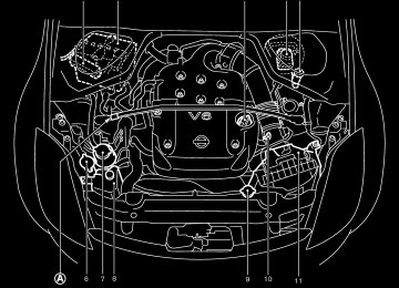
INSTRUMENT PANEL
11. Side ventilator (P.4-2) 12. VDC (Vehicle dynamic control) OFF switch (P.2-26) or TCS (Traction control system) OFF switch (P.2-26)
13. Fuel filler lid opener switch (P.3-10) 14. Hood lock release handle (P.3-8) 15. Fuse box (P.8-23) 16. Tilting steering wheel lock lever (P.3-12) 17. 18. Navigation system* or Instrument pocket
Ignition switch/steering lock (P.5-5)
(P.2-29)
(if so
19. Rear window and outside mirror equipped) defroster switch (P.2-21) 20. Heater/air conditioner control (P.4-3) 21. Audio system (P.4-6)/Clock (P.2-27) 22. Heated seat switch (P.2-25) 23. Hazard warning flasher switch (P.2-24) 24. Ashtray (P.2-28) or Tray (P.2-30) See the page indicated in parentheses for operating details. *: Refer
to the separate Navigation System
Owner’s Manual.
1. Headlight and turn signal switch (P.2-21) 2.
Instrument brightness control switch (P.2-23)
3. Driver supplemental air bag (P.1-6)/Horn
(P.2-24)
4. Meters/gauges (P.2-3)
SIC1943
5. Cruise control main/set switch (P.5-15) 6. Trip computer mode/setting switch (P.2-8) 7. Windshield wiper/washer switch (P.2-19) 8. Center ventilator (P.4-2) 9. Cup holder (P.2-30) 10. Passenger supplemental air bag (P.1-6)
2-2 Instruments and controls
Z 02.9.13/Z33-D/V5.0 X
METERS AND GAUGES
8. Automatic transmission position indicator or Manual transmission shift up indicator (See “Driving the vehicle” in the “5. Starting and driving” section.)
9. Reset knob for trip odometer 10.Odometer (Total/Twin trip) 11.Trip computer setting switch (See “Trip com-
puter” later in this section.)
12.Trip computer mode switch (See “Trip com-
puter” later in this section.)
Combination meter: 1. Warning/Indicator lights 2. Turn signal/hazard indicator lights 3. Tachometer 4. Speedometer
SIC1947
5.
Instrument brightness control switch (See “Headlight and turn signal switch” later in this section.)
6. Fuel gauge 7. Engine coolant temperature gauge
Instruments and controls 2-3
Z 02.9.13/Z33-D/V5.0 X
Changing the display: Pushing the reset knob changes the display as follows: TRIP A fi Resetting the trip odometer: Pushing the reset knob for more than 1 second resets the trip odometer to zero.
TRIP B fi
TRIP A
Triple meter: 1. Trip computer 2. Engine oil pressure gauge 3. Volt meter
2-4 Instruments and controls
SIC1948
SIC1949
SPEEDOMETER AND ODOMETER Speedometer The speedometer indicates vehicle speed. Odometer/Twin trip odometer The odometer/twin trip odometer are displayed when the ignition key is in the ON position. The odometer records the total distance the vehicle has been driven. The twin trip odometer records the distance of individual trips.
Z 02.9.13/Z33-D/V5.0 X
CAUTION
the normal
If the gauge indicates engine coolant temperature over range, stop the vehicle as soon as safely pos- sible. If the engine is overheated, con- tinued operation of the vehicle may se- riously damage the engine. See “If your vehicle overheats” in the “6. In case of emergency” section for immediate ac- tion required.
SIC1950
SIC1951
TACHOMETER The tachometer indicates engine speed in revo- lutions per minute (r/min).
CAUTION
When engine speed approaches the red zone, shift to a higher gear. Operating the engine in the red zone may cause serious engine damage.
ENGINE COOLANT TEMPERATURE GAUGE The gauge indicates the engine coolant tem- perature. The engine coolant temperature will vary with the outside air temperature and driving conditions.
Instruments and controls 2-5
Z 02.9.13/Z33-D/V5.0 X
The low fuel warning light comes on when the fuel tank is getting low. Refuel as soon as it is convenient, preferably before the gauge reaches E. There will be a small reserve of fuel in the tank when the fuel gauge needle reaches E. The cated on the passenger’s side of the vehicle.
indicates that the fuel filler lid is lo-
CAUTION
malfunction indicator
I If the vehicle runs out of fuel, the lamp (MIL) may come on. Refuel as soon as possible. After a few driving trips, the lamp should turn off. If the lamp remains on after a few driving trips, have the vehicle inspected by an authorized NISSAN dealer.
I For additional information, see the “Malfunction indicator lamp (MIL)” later in this section.
SIC1954
ENGINE OIL PRESSURE GAUGE The gauge indicates the engine lubrication sys- tem oil pressure while the engine is running. When the engine speed is high, the engine oil pressure is also high. When it is low, the gauge indicates the low oil pressure.
Z 02.9.13/Z33-D/V5.0 X
SIC1952
FUEL GAUGE The gauge indicates the approximate fuel level in the tank. The gauge may move slightly during braking, turning, acceleration, or going up or down hill. The gauge needle is designed to move to the E (Empty) position when the ignition key is turned to the OFF position. Refill the fuel tank before the gauge regis- ters Empty.
2-6 Instruments and controls
operation in such a condition could cause serious damage to the engine.
SIC1953
CAUTION
I This gauge is not designed to indi- cate low engine oil level. Use the dipstick to check the oil level. (See “Engine oil” in the “8. Maintenance and do-it-yourself” section.)
I If the gauge needle does not move with the proper amount of engine oil, have the vehicle checked by a NISSAN dealer. Continued vehicle
SIC1955
VOLT METER When the ignition switch is turned to the ON position, the volt meter indicates the battery voltage; while the engine is running, it indicates the alternator voltage of 11 - 15 volts (normal range qA ). However, while cranking the engine, the volts drop below the normal range. If the needle is not in the normal range qA while the engine is running, it may indicate that the charging system is not functioning properly. Have the system checked by a NISSAN dealer.
Instruments and controls 2-7
Z 02.9.13/Z33-D/V5.0 X
Stopwatch fi
consumption and speed fi Elapsed time and trip odometer fi Tire pressure indicator (PSI) (if so equipped) fi Up-shift indi- cator setting (for M/T models) fi Speed indica- tor Speed indicator (MPH or km/h) The vehicle speed is displayed in MPH or km/h while driving. Outside air temperature (ICY — °F or °C) The outside air temperature is displayed in °F or °C in the range of −22 to 131°F (−30 to 55°C).
The outside air temperature mode includes a low temperature warning feature: below 37°F (3°C), the outside air temperature mode is automati- cally selected and ICY indicator will illuminate in order to draw the driver’s attention. Press the mode switch qA if you wish to return to the mode that was selected before the warning occurred. The ICY indicator will continue blinking as long as the temperature remains below 39°F (4°C).
The ambient temperature sensor is located in front of the radiator. The sensor may be affected by road or engine heat, wind directions and other driving conditions. The display may differ from the actual ambient the
temperature or
SIC1956
SIC1957
TRIP COMPUTER The display of the trip computer is situated in the triple meter. When the ignition switch is turned to ON, the display scrolls all the modes of the trip computer and then shows the mode chosen before the ignition switch is turned OFF.
2-8 Instruments and controls
Switches for the trip computer are located on the side of the combination meter panel. To operate the trip computer, press the side of the switches as shown above. qA : Trip computer mode switch qB : Trip computer setting switch When the ignition switch is turned to ON, modes of the trip computer can be selected by pressing the trip computer mode switch qA . Each time the mode switch qA is pressed, the display will change as follows: Speed indicator temperature (ICY) fi Distance to empty (dte) fi Average fuel
Outside air
Z 02.9.13/Z33-D/V5.0 X
fi temperature displayed on various signs or bill- boards. Distance to empty (dte — mile or km) The distance to empty (dte) mode provides you with an estimation of the distance that can be driven before refueling. The dte is constantly being calculated, based on the amount of fuel in the fuel tank and the actual fuel consumption. The display is updated every 30 seconds. The dte mode includes a low range warning feature: when the fuel level is low, the dte mode is automatically selected and the digits blink in order to draw the driver’s attention. Press the mode switch qA if you wish to return to the mode that was selected before the warning occurred. The dte indicator will remain blinking until the vehicle is refuelled. When the fuel display will change to (----). NOTE: I If the amount of fuel added while the ignition switch is OFF is small, the dis- play just before the ignition switch is turned OFF may continue to be dis- played.
level drops even lower, the dte
I When driving uphill or rounding curves, the fuel in the tank shifts, which may
momentarily change the display.
Average fuel consumption (Mpg or l/100 km) The average fuel consumption mode shows the average fuel consumption since the last reset. Resetting is done by pressing the trip computer setting switch qB for more than approximately 1
second. (The average speed is also reset at the same time.) The display is updated every 30 seconds. At about the first 1/3 miles (500 m) after a reset, the display shows (----). Average speed (MPH or km/h) The average speed mode shows the average vehicle speed since the last reset. Resetting is done by pressing the setting switch qB for more than approximately 1 second. (The average fuel consumption is also reset at the same time.) The display is updated every 30 seconds. The first 30 seconds after a reset, the display shows (----). Elapsed time (h:m:s) The elapsed time mode shows the time since the last reset. The displayed time can be reset by pressing the trip computer setting switch qB for more than approximately 1 second. (The tripodometer is also reset at the same time.) Trip odometer (MLS or km) The trip odometer mode shows the total dis- tance the vehicle has been driven since the last reset. Resetting is done by pressing the setting switch qB for more than approximately 1 second. (The elapsed time is also reset at the same time.) Stopwatch (h:m:s) You can use the trip computer as a stopwatch. Each time the trip computer setting switch qB is pressed, the stopwatch will be operated as follows:
After 100 hours, the time will start from the reset display again. Even if the display is switched to the other mode while the time is starting, the stopwatch contin- ues to advance until you stop the time in the stopwatch mode. When the ignition switch is turned OFF, the time is reset. Tire pressure indicator (PSI) (if so equipped) The tire pressure indicator shows tire pressure (0 - 51 psi) of all wheels (except the spare tire) Instruments and controls 2-9
Z 02.9.13/Z33-D/V5.0 X
second will add the figure by 100 rpm. If press- ing for more than approximately 1 second, the figure will increase by 500 rpm. If the battery cable is disconnected, the set engine speed will be returned to the initial figure (6,600 rpm). Display priority If a low outside air temperature warning, low dte (distance to empty) range warning and low tire pressure warning occur simul- taneously, other display modes switch au- tomatically to the outside air temperature display. When trip computer mode switch qA is pressed, the display switches to the mode chosen before the warning display, but the ICY indicator will continue blinking.
by sending a signal from a sensor that is installed in each wheel. Press the trip computer setting switch qB to change the display to F (front) or R (rear). The tire pressure sensor will activate only when the vehicle is driven at speeds above 20 MPH (32 km/h). If the tire pressure signal cannot be received correctly, the display shows (----). The tire pressure indicator mode includes a low tire pressure warning feature. If the vehicle is being driven with very low tire pressure or a flat tire, the tire pressure indicator mode is automati- cally selected and the PSI indicator will blink in order to attract the driver’s attention. Press the trip computer mode switch qA if you wish to return to the mode that was selected before the warning occurred. The PSI indicator will con- tinue blinking until the tire pressure of each tire is properly adjusted. For additional information, see “Low tire pres- sure warning system” in the “5. Starting and driving” section and “Flat tire” in the “6. In case of emergency” section. Tire pressure shown in the display may rise or fall while driving depending on the driv- ing conditions (heat, etc.) and/or the out- side temperature. This does not indicate a system malfunction.
2-10 Instruments and controls
WARNING
The low tire pressure warning system is not a substitute for the regular tire pres- sure check. Be sure to check the tire pressure regularly and adjust it to the COLD tire pressure shown in the tire placard.
Up-shift indicator setting (rpm) (for manual transmission models) The up-shift indicator setting mode is used to set the desired engine speed (rpm) for the up-shift indicator (situated in the tachometer) to illuminate. When the engine speed approaches or reaches the set figure, the up-shift indicator will flash or illuminate to show the driver the timing for shifting into a higher gear. See “Driving the vehicle” in the “5. Starting and driving” section for the use of the up-shift indicator. When the up-shift indicator setting mode is selected, the rpm indicator blinks and the engine speed currently set (The initial factory setting is 6,600 rpm.) The figure can be changed between 2,000 and 8,000 rpm by pressing trip computer setting switch qB . Press- ing the switch for less than approximately 1
is displayed.
Z 02.9.13/Z33-D/V5.0 X
WARNING/INDICATOR LIGHTS AND AUDIBLE REMINDERS
or
or
Anti-lock brake warning light
Low washer fluid warning light
Malfunction indicator lamp (MIL)
Automatic transmission check warning light
Seat belt warning light
Slip indicator light
Brake warning light
Supplemental air bag warning light
Charge warning light
Door open warning light
Engine oil pressure warning light
Low tire pressure warning light (if so equipped)
Automatic transmission position indicator light Cruise main switch indicator light (if so equipped) Cruise set switch indicator light (if so equipped)
High beam indicator light (Blue)
Traction control system off indicator light (if so equipped) Vehicle dynamic control off indicator light (if so equipped)
Turn signal/hazard indicator lights
CHECKING BULBS Apply the parking brake and turn the ignition key to ON without starting the engine. The following lights will come on:
or
The following lights come on briefly and then go off:
or
If any light fails to come on, it may indicate a burned-out bulb or an open circuit in the elec-
system. Have the system repaired
trical promptly. WARNING LIGHTS
or
Anti-lock brake warning light
After turning the ignition key to the ON position, the light will illuminate. The light will turn off after about 1 second if the system is operational.
If the light comes on while the engine is running, it may indicate the anti-lock brake system is not
functioning properly. Have the system checked by your NISSAN dealer. If an abnormality occurs in the system, the anti-lock function will cease but the ordinary brakes will continue to operate normally. See “Anti-lock brake system (ABS)” in the “5. Start- ing and driving” section for further details. If the light comes on while you are driving, contact your NISSAN dealer for repair.
Instruments and controls 2-11
Z 02.9.13/Z33-D/V5.0 X
Automatic transmission check warning light (A/T models)
When the ignition switch is turned ON, the light comes on for 2 seconds. If the light blinks for approximately 8 seconds, it may indicate the automatic transmission system is not functioning properly. Have your NISSAN dealer check and repair the transmission.
or
Brake warning light
This light functions for both the parking brake and the foot brake systems. Parking brake indicator: When the ignition key is in the ON position, the light comes on when the parking brake is ap- plied. Low brake fluid warning light: The light warns of a low brake fluid level. If the light comes on while the engine is running with the parking brake not applied, stop the vehicle and perform the following: 1. Check the brake fluid level. Add brake fluid as necessary. See “Brake and clutch fluid” in the “8. Maintenance and do-it-yourself” section.
2-12 Instruments and controls
WARNING
I Your brake system may not be work- ing properly if the warning light is on. Driving could be dangerous. If you judge it to be safe, drive carefully to the nearest service station for re- pairs. Otherwise, have your vehicle towed because driving it could be dangerous.
I Pressing the brake pedal with the engine stopped and/or low brake fluid level may increase your stop- ping distance and braking will re- quire greater pedal effort as well as greater pedal travel.
I If the brake fluid level is below the MIN mark on the brake fluid reser- voir, do not drive until the brake sys- tem has been checked at a NISSAN dealer.
2.
If the brake fluid level is correct, have the warning system checked by a NISSAN dealer. Avoid high speed driving and abrupt braking. If both the brake warning light and the anti-
lock brake warning light come on simulta- neously, it may indicate the anti-lock brake system is not functioning properly. See “Anti- lock brake warning light” earlier in this sec- tion.
Charge warning light
If the light comes on while the engine is running, it may indicate that the charging system is not functioning properly. Turn the engine off and check the alternator belt. If the belt is loose, broken, missing or if the light remains on, see your NISSAN dealer immediately.
CAUTION
Do not continue driving if the belt is loose, broken or missing.
Door open warning light
This light comes on when any of the doors and/or rear hatch are not closed securely while the ignition key is ON.
Engine oil pressure warning light
This light warns of low engine oil pressure. If the light flickers or comes on during normal driving, pull off the road in a safe area, stop the engine
Z 02.9.13/Z33-D/V5.0 X
immediately and call a NISSAN dealer or other authorized repair shop. The engine oil pressure warning light is not designed to indicate a low oil level. Use the dipstick to check the oil level. See “Engine oil” in the “8. Maintenance and do-it-yourself” section.
CAUTION
Running the engine with the engine oil pressure warning light on could cause serious damage to the engine almost immediately. Turn off the engine as soon as it is safe to do so.
Low tire pressure warning light (if so equipped)
The light comes on for about 1 second when the key switch is turned ON, and then it turns off. If the vehicle is being driven with a flat tire or extremely low tire pressure, the light will illumi- nate. Also a chime will sound for about 10
seconds if a tire is flat. For additional information, see “Low tire pres- sure warning system” in the “5. Starting and driving” section and “Flat tire” in the “6. In caseof emergency” section. Also, you can check the tire pressure of all 4 tires on the trip computer display. See “Trip computer” earlier in this sec- tion.
WARNING
I If the light does not come on with the key switch turned ON, have the ve- hicle checked by a NISSAN dealer as soon as possible.
I If the light comes on while driving, avoid sudden steering maneuvers or abrupt braking, reduce vehicle speed, pull off the road to a safe location and stop the vehicle as soon as pos- sible. Serious vehicle damage could occur and may lead to an accident and could result in serious personal injury. Check the pressure for all four tires and adjust the pressure to the COLD tire pressure shown on the tire placard. If the light still comes on while driving after adjusting the tire pressure, a tire may be flat. If you have a flat tire, replace it with a spare tire as soon as possible.
I When a spare tire is mounted or a wheel is replaced, tire pressure will not be indicated and the low tire pressure warning system will not function. Contact your NISSAN dealer as soon as possible for tire replacement and/or system reset- ting.
CAUTION
I The low tire pressure warning is not a substitute for the regular tire pres- sure check. Be sure to check the tire pressure regularly.
I If
the vehicle is being driven at less than 20 MPH (32
speeds of km/h), the low tire pressure warning system may not operate correctly.I Be sure to install the specified size
for the front and rear tires.
Low washer fluid warning light This light comes on when the washer tank fluid is Instruments and controls 2-13
Z 02.9.13/Z33-D/V5.0 X
at a low level. Add washer fluid as necessary. See “Window washer fluid” in the “8. Mainte- nance and do-it-yourself” section.
Seat belt warning light and chime
The light and chime remind you to fasten seat belts. The light illuminates whenever the ignition key is turned to ON, and will remain illuminated until the driver’s seat belt is fastened. See “Seat belts” in the “1. Seats, restraints and supplemental air bag systems” section for pre- cautions on seat belt usage.
Supplemental air bag warning light
After turning the ignition key to the ON position, the supplemental air bag warning light will illu- minate. The supplemental air bag warning light will turn off after about 7 seconds if the system is operational. If any of the supplemental front air bag, supplemental side air bag and curtain side-impact air bag systems, and pre-tensioner seat belt need servicing and your vehicle must be taken to your nearest NISSAN dealer. I The supplemental air bag warning light re-
the following conditions occur,
mains on after approximately 7 seconds.
I The supplemental air bag warning light
flashes intermittently.
I The supplemental air bag warning light does
not come on at all.
Unless checked and repaired, the Supplemental Restraint Systems and/or the pre-tensioner seat belt may not function properly. For additional information, see “Supplemental restraint system” in the “1. Seats, restraints and supplemental air bag systems” section.
WARNING
is on,
it could mean that
If the supplemental air bag warning light the supplemental front air bag, supplemen- tal side air bag and curtain side-impact air bag systems and/or pre-tensioner seat belt system will not operate in an accident.
INDICATOR LIGHTS
Automatic transmission position indicator light (A/T models)
When the ignition key is turned to the ON
position, the indicator in the tachometer shows the automatic transmission selector lever posi- tion. See “Driving with automatic transmission” in the “5. Starting and driving” section.
Cruise main switch indicator light (if so equipped)
The light comes on when the cruise control main switch is pushed. The light goes out when the main switch is pushed again. When the cruise main switch indicator light comes on, the cruise control system is operational.
Cruise set switch indicator light (if so equipped)
The light comes on while the vehicle speed is controlled by the cruise control system. If the light blinks while the engine is running, it may indicate the cruise control system is not func- tioning properly. Have the system checked by your NISSAN dealer.
High beam indicator light (Blue)
This light comes on when the headlight high beam is on and goes out when the low beam is selected.
2-14 Instruments and controls
Z 02.9.13/Z33-D/V5.0 X
Malfunction indicator lamp (MIL)
the malfunction indicator
If lamp comes on steady or blinks while the engine is running, it may indicate a potential emission control mal- function.
The malfunction indicator lamp may also come on steady if the fuel filler cap is loose or missing, or if the vehicle runs out of fuel. Check to make sure the fuel filler cap is installed and closed tightly, and that the vehicle has at least 3 US gallons (14 liters) of fuel in the fuel tank.
After a few driving trips, the lamp should turn off if no other potential emission control system malfunction exists.
Operation
The malfunction indicator lamp will come on in one of two ways: I Malfunction indicator lamp on steady — An emission control system malfunction has been detected. Check the fuel filler cap. If the fuel filler cap is loose or missing, tighten or install the cap and continue to drive the vehicle. The lamp should turn off after a few driving trips. If the lamp does not turn off after a few driving trips, have the vehicle inspected by a NISSAN dealer. You
do not need to have your vehicle towed to the retailer.
I Malfunction indicator lamp blinking — An engine misfire has been detected which may damage the emission control system. To re- duce or avoid emission control system dam- age: a) Do not drive at speeds above 45 MPH
(72 km/h).
b) Avoid hard acceleration or deceleration. c) Avoid steep uphill grades. d) If possible, reduce the amount of cargo
being hauled or towed. The malfunction indicator blinking and come on steady. Have the vehicle inspected by a NISSAN dealer. You do not need to have your vehicle towed to the retailer.
lamp may stop
CAUTION
Continued vehicle operation without having the emission control system checked and repaired as necessary could lead to poor driveability, reduced fuel economy, and possible damage to the emission control system.
Slip indicator light
The light will come on for about 1 second and go off after the ignition switch is turned to the ON position. This light will blink when the vehicle dynamic control (VDC) system or the traction control system (TCS) is operating, thus alerting the driver to the fact that the road surface is slippery and the vehicle is nearing its traction limits.
Traction control system off indicator light (if so equipped) After turning the ignition key to the ON position, the light will illuminate. The light will turn off in about 1 second if the traction control system (TCS) is operational. The light comes on when the traction control system (TCS) off switch is pushed to OFF. This indicates the traction control system is not op- erating. When the traction control system off indicator light and slip indicator light come on with the traction control system turned on, this light alerts the driver to the fact that the traction control system’s fail-safe mode is operating, that is the system may not be functioning properly. Have the system checked by your NISSAN dealer. If an abnormality occurs in the system, the traction control function will be canceled but the vehicle is still driveable. For additional infor- Instruments and controls 2-15
Z 02.9.13/Z33-D/V5.0 X
SECURITY SYSTEMS
Your vehicle has two types of security systems, as follows: I Vehicle Security System I Nissan Vehicle Immobilizer System (NVIS)
mation, see “Traction control system (TCS)” in the “5. Starting and driving” section of this manual.
Vehicle dynamic control off indicator light (if so equipped) After turning the ignition key to the ON position, the light will illuminate. The light will turn off in about 1 second if the vehicle dynamic control (VDC) system is operational. The light comes on when the vehicle dynamic control (VDC) off switch is pushed to OFF. This indicates the vehicle dynamic control system and traction control system are not operating. When the vehicle dynamic control off indicator light and slip indicator light come on with the vehicle dynamic control system turned on, this light alerts the driver to the fact that the vehicle dynamic control system’s fail-safe mode is op- erating, that is the system may not be functioning properly. Have the system checked by your NISSAN dealer. If an abnormality occurs in the system, the vehicle dynamic control system function will be canceled but the vehicle is still driveable. For additional information, see “Ve- hicle dynamic control (VDC) system” in the “5. Starting and driving” section of this manual.
Turn signal/hazard indicator lights
The light flashes when the turn signal switch lever or hazard switch is turned on. AUDIBLE REMINDERS Key reminder chime The chime will sound if the driver’s side door is opened while the key is left in the ignition switch (ignition switch is turned off). Remove the key and take it with you when leaving the vehicle. Light reminder chime The chime will sound when the driver’s door is opened with the headlight switch on unless the key is in the ignition switch. Make sure to turn the light switch off when you leave the vehicle. Brake pad wear warning The disc brake pads have audible wear warn- ings. When a brake pad requires replacement, it will make a high pitched scraping sound when the vehicle is in motion whether or not the brake pedal is depressed. Have the brakes checked as soon as possible if the warning sound is heard.
2-16 Instruments and controls
Z 02.9.13/Z33-D/V5.0 X
2. Remove the key from the ignition switch.
3. Close and lock all doors, hood and rear
hatch.
Lock all doors by pressing the LOCK button on the keyfob. When using the keyfob, the hazard indicators flash twice to indicate all doors are locked.
4. Confirm that
the security indicator
light comes on. The security indicator light glows for about 30 seconds and then blinks. The system is now activated. If, during this 30
second time period, the door is unlocked by the key or the keyfob, or the ignition key is turned to ACC or ON, the system will not activate.I If the key is turned slowly toward the rear of the vehicle when locking the door, the system may not activate. If the key is returned beyond the vertical po- sition toward the front of the vehicle to remove the key, the system may be deactivated. If the indicator light fails to glow for 30 seconds, unlock the door once and lock it again.
I Even when the driver and/or passengers are in the vehicle, the system will acti- vate with all doors, hood and rear hatch locked and ignition key off. Turn the
ignition key to ACC to turn the system off.
Vehicle security system operation The security system will give the following alarm: I The headlights blink and the horn sounds
intermittently.
I The alarm automatically turns off after ap- proximately 1 minute. However, the alarm reactivates if the vehicle is tampered with again. The alarm can be shut off by unlocking a door with the key, or by pressing the UNLOCK button on the keyfob.
The alarm is activated by: I Opening the door without using the key or
keyfob.
I Opening the rear hatch without using the rear
hatch release switch or keyfob.
I Opening the hood. How to stop alarm The alarm will stop only by unlocking a door with the key, or by pressing the UNLOCK button on keyfob. The alarm will not stop if the ignition switch is turned to ACC or ON. If the system does not operate as de- Instruments and controls 2-17
Z 02.9.13/Z33-D/V5.0 X
SIC1699
The security condition will be shown by the security indicator light. VEHICLE SECURITY SYSTEM The vehicle security system provides visual and audio alarm signals if parts of the vehicle are disturbed. How to activate the vehicle security system 1. Close all windows. The system can be activated even if the windows are open.
Nissan Vehicle Immobilizer System key on a separate key ring to avoid interference from other devices.
Statement related to section 15 of FCC rules for Nissan Vehicle Immobilizer Sys- tem (CONT ASSY-BCM, ANT ASSY- IMMOBILIZER) This device complies with part 15 of the FCC Rules and RSS-210 of Industry Canada. Operation is subject to the follow- ing two conditions; (1) This device may not cause harmful in- terference, and (2) this device must accept any interference received, including inter- ference that may cause undesired opera- tion of the device. CHANGES OR MODIFICATIONS NOT EX- PRESSLY APPROVED BY THE MANUFAC- TURE RESPONSIBLE FOR COMPLIANCE COULD VOID THE USER’S AUTHORITY TO OPERATE THE EQUIPMENT.
scribed above, have it checked by your NISSAN dealer. NISSAN VEHICLE IMMOBILIZER SYSTEM (NVIS) The Nissan Vehicle Immobilizer System will not allow the engine to start without the use of the registered Nissan Vehicle Immobilizer System key.
If the engine fails to start using the registered Nissan Vehicle Immobilizer System key, it may be due to interference caused by another Nissan Vehicle Immobilizer System key, an automated toll road device or automated payment device on the key ring. Restart the engine using the follow- ing procedures:
1. Leave the ignition switch in the ON position
for approximately 5 seconds.
2. Turn the ignition switch to the OFF or LOCK position and wait approximately 10 seconds.
3. Repeat step 1 and 2 again. 4. Restart the engine while holding the device (which may have caused the interference) separate from the registered Nissan Vehicle Immobilizer System key. If this procedure allows the engine to start, NISSAN recommends placing the registered
2-18 Instruments and controls
SIC1699
Security indicator light This light blinks whenever the ignition switch is in the LOCK, OFF or ACC position. This function indicates the security system equipped on the vehicle is operational.
If the Nissan Vehicle Immobilizer System is malfunctioning, this light will remain on while the ignition key is in the ON position. If the light still remains on and/or the engine will not start, see your NISSAN dealer for Nissan Vehicle Immobilizer Sys- tem service as soon as possible. Please bring all Nissan Vehicle Immobilizer Sys-
Z 02.9.13/Z33-D/V5.0 X
tem keys that you have when visiting your NISSAN dealer for service.
WINDSHIELD WIPER AND WASHER SWITCH
SIC1958
The windshield wiper and washer operates when the ignition key is in the ON position.
Push the lever down to operate the wiper at the following speed: q1 Intermittent — intermittent operation can be adjusted by turning the knob toward qA (Slower) or qB (Faster). Also, the intermittent operation speed varies in accordance with the vehicle speed. (For example, when the vehicle speed is high, the intermittent opera- tion speed will be faster.)
q2 Low — continuous low speed operation q3 High — continuous high speed operation
Push the lever up q4 to have one sweep opera- tion of the wiper. Pull the lever toward you q5
to operate the washer. Then the wiper will also operate several times.WARNING
In freezing temperatures the washer so- lution may freeze on the windshield and obscure your vision which may lead to an accident. Warm the windshield with the defroster before you wash the wind- shield.
CAUTION
The following could damage the washer system: I Do not operate the washer continu-
ously for more than 30 seconds.
I Do not operate the washer if the
reservoir tank is empty.
Instruments and controls 2-19
Z 02.9.13/Z33-D/V5.0 X
REAR WINDOW WIPER AND WASHER SWITCH
CAUTION
before you wash.
I If the rear window wiper operation is interrupted by snow etc., the wiper may stop moving to protect its motor. If this occurs, turn the wiper switch to OFF and remove the snow etc. on and around the wiper arms. After about 1 minute, turn the switch ON again to operate the wiper.
I Do not operate the washer continu-
ously for more than 30 seconds.
I Do not operate the washer if reser-
voir tank is empty.
I Do not operate the washer when the
rear hatch is open.
WARNING
In freezing temperatures the washer so- lution may freeze on the rear window glass and obscure your vision. Warm the rear window glass with the defroster
SIC1959
The rear window wiper and washer operate when the ignition switch is in the ON position. Turn the switch clockwise from the OFF position to operate the wiper. q1 Intermittent — intermittent operation (not ad-
justable)
q2 Low — continuous low speed operation Push the switch forward q3
to operate the washer. Then the wiper will also operate several times.2-20 Instruments and controls
Z 02.9.13/Z33-D/V5.0 X
REAR WINDOW AND OUTSIDE MIRROR (if so equipped) DEFROSTER SWITCH
SIC1960
To defog/defrost the rear window glass and outside mirrors (if so equipped), start the engine and push the switch on. The indicator light will come on. Push the switch again to turn the defroster off. It will automatically turn off in approximately 15
minutes.CAUTION
When cleaning the inner side of the rear window, be careful not to scratch or damage the rear window defroster.
HEADLIGHT AND TURN SIGNAL SWITCH XENON HEADLIGHTS (if so equipped)
WARNING
HIGH VOLTAGE
I When xenon headlights are on, they produce a high voltage. To prevent an electric shock, never attempt to modify or disassemble. Always have your xenon headlights replaced at a NISSAN dealer.
I Xenon headlights provide consider- ably more light than conventional headlights. If they are not correctly aimed, they might temporarily blind an oncoming driver or the driver ahead of you and cause a serious accident. If headlights are not aimed correctly, immediately take your ve- hicle to a NISSAN dealer and have the headlights adjusted correctly.
When the xenon headlight is initially turned on, its brightness or color varies slightly. However, the color and brightness will soon stabilize.
I The life of xenon headlights will be shortened by frequent on-off operation. It is generally desirable not to turn off the headlights for short intervals (for example, when the vehicle stops at a traffic signal). Even when the daytime running lights are active (Canada only), the xenon headlights do not turn on. This way the life of the xenon headlights is not reduced.
I If the xenon headlight bulb is close to burning out, the brightness will drasti- cally decrease, the light will start blink- ing, or the color of the light will become reddish. If one or more of the above signs appear, contact a NISSAN dealer.
Instruments and controls 2-21
Z 02.9.13/Z33-D/V5.0 X
been turned to the OFF position.
or
I When the headlight switch remains in the position after the lights auto- matically turn off, the lights will turn on for 5
minutes when the headlight switch is turned to the OFF position and turn to the orposition.
CAUTION
I Be sure to turn the light switch to the OFF position when you leave the ve- hicle for extended periods of time, otherwise the battery will go dead.
I Never leave the light switch on when the engine is not running for ex- tended periods of time even if the headlights turn off automatically.
SIC1961
SIC1962
HEADLIGHT SWITCH Lighting q1 Turn the switch to the
position:
The front park, side marker, tail, license plate and instrument lights will come on.
q2 Turn the switch to the
position:
Headlights will come on and all the other lights remain on.
2-22 Instruments and controls
Headlight beam select q1 To select the low beam, put the lever in the
neutral position as shown.
q2 To select the high beam, push the lever forward. Pull it back to select the low beam. q3 Pulling the lever toward you will flash the
headlight high beam. Battery saver system I When the headlight switch is in the
or position while the ignition switch is in the ON position, the lights will automatically turn off 5 minutes after the ignition switch has
Z 02.9.13/Z33-D/V5.0 X
DAYTIME RUNNING LIGHT SYSTEM (CANADA ONLY) The headlights automatically illuminate at a re- duced intensity when the engine is started with the parking brake released. The daytime running lights operate with the headlight switch in the OFF position or in the position. Turn the headlight switch to the position for full illumination when driving at night. If the parking brake is applied before the engine is started, the daytime running lights do not illuminate. The daytime running lights illuminate once the parking brake is released. The daytime running lights will remain on until the ignition switch is turned off.
WARNING
When the daytime running light system is active, tail lights on your vehicle are not on. It is necessary at dusk to turn on your headlights. Failure to do so could cause an accident injuring yourself and others.
SIC1963
SIC1964
TURN SIGNAL SWITCH q1 Turn signal Move the lever up or down to signal the turning direction. When the turn is completed, the turn signals cancel automatically. q2 Lane change signal To indicate a lane change, move the lever up or down to the point where lights begin flashing.
INSTRUMENT BRIGHTNESS CONTROL The instrument brightness control operates when the light switch is in the or
position.
To adjust the brightness of instrument panel lights, press the control switches located on the left side of the meter panel. Pressing the upper switch qA will brighten the lights. The lower switch qB will darken the lights. The brightness can be adjusted to 5 different levels, 0 (no lights) - 4 (maximum).
Instruments and controls 2-23
Z 02.9.13/Z33-D/V5.0 X
HAZARD WARNING FLASHER SWITCH
HORN
I Do not use the hazard warning flash- ers while moving on the highway un- less unusual circumstances force you to drive so slowly that your vehicle might become a hazard to other traf- fic.
I Turn signals do not work when the hazard warning flasher lights are on.
The flasher can be actuated with the ignition switch either off or on.
SIC1447
Push the switch (located on the center console) on to warn other drivers when you must stop or park under emergency conditions. All turn signal lights will flash. Some state or provincial laws may prohibit the use of the hazard warning flasher switch while driving.
WARNING
I If stopping for an emergency, be sure to move the vehicle well off the road.
2-24 Instruments and controls
To sound the horn, push the center pad area of the steering wheel.
SIC1965
WARNING
Do not disassemble the horn. Doing so could affect proper operation of the supplemental front air bag system. Tam- pering with the supplemental front air bag system may result in serious per- sonal injury.
Z 02.9.13/Z33-D/V5.0 X
damage to the heater.
I Any liquid spilled on the heated seat should be removed immediately with a dry cloth.
I When cleaning the seat, never use gasoline, thinner, or any similar ma- terials.
I If any abnormalities are found or the heated seat does not operate, turn the switch off and have the system checked by your NISSAN dealer.
HEATED SEATS (if so equipped)
SIC1966
The front seats are warmed by built-in heaters. The switches located on the center console can be operated independently of each other.
1. Start the engine.
2. Select heat range.
I For low heat, press the
(Low) side
of the switch.
I For high heat, press the
(High) side
of the switch.
I For no heat, the switch has a center OFF
position between low and high.
The indicator light in the switch will illuminate
when low or high is selected.
The heater is controlled by a thermostat, automatically turning the heater on and off. The indicator light will remain on as long as the switch is on.
3. When the vehicle’s interior is warmed, or before you leave the vehicle, be sure to turn the switch to the OFF position (center).
CAUTION
I The battery could run down if the seat heater is operated while the en- gine is not running.
I Do not use the seat heater for ex- tended periods or when no one is using the seat.
I Do not put anything on the seat which insulates heat, such as a blan- ket, cushion, seat cover, etc. Other- wise, the seat may become over- heated.
I Do not place anything hard or heavy on the seat or pierce it with a pin or similar object. This may result in
Instruments and controls 2-25
Z 02.9.13/Z33-D/V5.0 X
VEHICLE DYNAMIC CONTROL (VDC) OFF SWITCH (if so equipped)
TRACTION CONTROL SYSTEM (TCS) OFF SWITCH (if so equipped)
engine to turn ON the system. See “Vehicle dynamic control (VDC) system” in the “5. Start- ing and driving” section.
SIC1881
The vehicle should be driven with the Vehicle Dynamic Control (VDC) System ON for most driving conditions. When the vehicle is stuck in mud or snow, the VDC system reduces the engine output to re- duce wheel spin. The engine speed will be reduced even if the accelerator is depressed to the floor. If maximum engine power is needed to free a stuck vehicle, turn the VDC system off. To cancel the Vehicle Dynamic Control (VDC) System, push the VDC OFF switch to turn off the system. The indicator light will come on. Push the VDC OFF switch again or restart the 2-26 Instruments and controls
SIC1967
To cancel the Traction Control System (TCS), indicator push the TCS OFF switch. The light will come on. Push it again or restart the engine to turn the system back on. See “Traction control system (TCS)” in the “5. Starting and driving” section.
Z 02.9.13/Z33-D/V5.0 X
CLOCK
POWER OUTLET
) to adjust the hour. Press the TUNE the side will side
button qC minute. Pressing the advance the time and the will turn back the time.
to adjust
or
or
4. Press the DISP button qA to finish the adjust-
ment.
Resetting During the clock adjustment mode, pressing the DISP qA and TUNE qC buttons will reset the time to a time signal. For example, if these buttons are pressed while the time is between 8:00 and 8:29, the display will be reset is between 8:30 and 8:59, the display will be reset to 9:00. At the same time the display will return to the previous audio mode.
If pressed while it
to 8:00.
The power outlet is for powering electrical ac- cessories such as cellular telephones.
SIC1968
CAUTION
I Use caution as the socket and plug may be hot during or immediately after use.
I This power outlet is not designed for
use with a cigarette lighter unit.
I Do not use with accessories that ex- ceed a 12 volt, 120W (10A) power
Instruments and controls 2-27
Z 02.9.13/Z33-D/V5.0 X
SIC1981
The digital clock (in the audio unit) displays time when the ignition key is in the ACC or ON position. If the power supply is disconnected, the clock will not indicate the correct time. Readjust the time. ADJUSTING THE TIME Adjust the time in the following steps: 1. Turn the audio unit on. 2. Keep pressing the DISP (Clock) button qA
until the clock display starts to flash. 3. Press the SEEK/TRACK button qB (
CIGARETTE LIGHTER AND ASHTRAY (accessory)
SIC1969
The cigarette lighter unit (including the socket) and ashtray are accessories. A genuine NISSAN cigarette lighter unit and/or ashtray can be pur- chased from a NISSAN dealer. The cigarette lighter operates when the ignition switch is in the ACC or ON position. Push the lighter in all the way. When the lighter is heated, it will spring out. Return the lighter to its original position after use.
draw. Do not use double adapters or more than one electrical accessory. I Use this power outlet with the engine running. (If the engine is stopped, this could result in a discharged bat- tery.)
I Avoid using when the air conditioner, headlights or rear window defroster is on.
I Before inserting or disconnecting a plug, be sure to turn off the power switch of electrical accessory being used or the ACC power of the vehicle. I Push the plug in as far as it will go. If good contact is not made, the plug may overheat or the internal tem- perature fuse may blow.
I When not in use, be sure to close the cap. Do not allow water to contact the socket.
2-28 Instruments and controls
WARNING
The cigarette lighter should not be used while driving so full attention may be given to vehicle operation.
CAUTION