- 2008 Mini Cooper Owners Manuals
- Mini Cooper Owners Manuals
- 2007 Mini Cooper Owners Manuals
- Mini Cooper Owners Manuals
- 2004 Mini Cooper Owners Manuals
- Mini Cooper Owners Manuals
- 2005 Mini Cooper Owners Manuals
- Mini Cooper Owners Manuals
- 2006 Mini Cooper Owners Manuals
- Mini Cooper Owners Manuals
- 2003 Mini Cooper Owners Manuals
- Mini Cooper Owners Manuals
- 2009 Mini Cooper Owners Manuals
- Mini Cooper Owners Manuals
- 2002 Mini Cooper Owners Manuals
- Mini Cooper Owners Manuals
- Download PDF Manual
-
107
CHANGING TIRES — MINI WITH SPACE-SAVER SPARE TIRE*
Preparing the vehicle
Read and comply with the safety precautions provided on page 106.<
1. Secure the vehicle to prevent it from
rolling: Place the folding chock behind the front wheel on the other side of the vehicle; on downward inclines, place it in front of this wheel. If the wheel is changed on a surface with a more severe slope, take additional precautions to secure the vehicle from rolling
2. Loosen the lug bolts by a half turn.
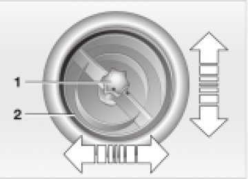
Jacking up the vehicle 1. Place the jack at the jacking point closest
to the wheel. The jack base must be perpendicular to the surface beneath the jacking point
9. Pull out the space-saver spare tire towards the rear underneath the vehicle
10. Position the space-saver spare tire with
the valve facing upwards
11. Unscrew the valve extension from the
valve of the space-saver spare tire
12. Unscrew the dust cap from the exten-
sion and attach to the space-saver spare tire.
108
CHANGING TIRES — MINI WITH SPACE-SAVER SPARE TIRE*
2. Insert the jack head for jacking up in the
square recess of the jacking point
3. Jack the vehicle up until the wheel you are changing is raised from the ground.
The vehicle jack is designed for changing wheels only. Do not
attempt to raise another vehicle model with it or to raise any load of any kind. To do so could cause accidents and personal injury.<
Fitting the space-saver spare tire 1. Unscrew the lug bolts and remove the
wheel
2. Remove accumulations of mud or dirt
from the mounting surfaces of the wheel and hub. Clean the lug bolts
3. Fit the space-saver spare tire 4. Screw at least two lug bolts finger-tight
into opposite bolt holes
5. Screw in the remaining bolts 6. Tighten all the lug bolts firmly in a diag-
onal pattern
7. Lower the vehicle 8. Remove the jack.
Tightening the lug bolts Tighten the lug bolts in a diagonal pattern.
As soon as possible, have the secure seating of the lug bolts (tightening torque 72 ftlb (100 Nm)) checked using a calibrated torque wrench. Otherwise, a wheel that might come loose can lead to a severe accident.<
Replace the defective tire as soon as possible and have the new wheel/tire assembly balanced.
Driving with the space-saver spare tire Drive cautiously. Do not exceed a speed of 50 mph (80 km/h). You can expect changes in vehicle handling such as delayed braking response, longer braking distances, and changes in self- steering properties in marginal stability limits.
Only one space-saver spare tire may be mounted at one time. Reinstall
wheels and tires of the same size and speci- fication as soon as possible. Maintain prescribed tire pressures, see page 80.<
Only use full hubcaps approved by the manufacturer. Otherwise there is no guarantee that the hubcap fits securely. The hubcap must not be fitted to the space- saver spare tire, as it could be damaged.<
Check and correct the tire inflation pressure at the earliest opportu-
nity.<
109
Continuing driving with a damaged tire Driving can continue under certain condi- tions with safety tires, depending on the vehicle load and the severity of the tire damage, at a maximum speed of 50 mph (80 km/h). You can determine the possible mileage for continued driving on the basis of the following general indications: > Tire inflation pressure 0 bar (0 psi):
approx. 95 miles (150 km)
> Tire inflation pressure 0.5 bar — 1 bar (7.2 psi — 14.5 psi): approx. 300 miles (500 km)
> Tire inflation pressure greater than 1 bar (14.5 psi): approx. 600 miles (1,000 km).
FLAT TIRE — SAFETY (RUN-FLAT) TIRES*
Flat tire The yellow indicator lamp in the instru- ment cluster lights up to indicate a flat tire. In addition, a gong sounds, see pages 17, 62. 1. Reduce vehicle speed carefully to under 50 mph (80 km/h), avoiding hard brake applications and steering maneuvers
2. Do not exceed a speed of 50 mph
(80 km/h)
3. Identify damaged tires; check tire infla- tion pressures on all four wheels at the next opportunity, see page 80
4. Correct the tire inflation pressure if you wish to continue your journey and this is permitted, see next column
5. Have damaged tires changed by your
MINI center, see page 84.
Your MINI center has the information needed for working with safety tires and is equipped with the necessary special tools. They provide advice if you wish to replace the tires on your MINI or wish to re-equip from summer to winter tires — or vice versa, see also pages 80, 84, 85.<
For safety reasons, do not have a damaged safety tire repaired.<
You will recognize safety tires by a circular symbol containing the letters RSC on the side of the tire. Safety tires consist of self-contained tires and special rims. The tire reinforcement ensures that the tire retains some residual safety in the event of pressure drop and driving remains possible to a restricted degree.
The reinforcement on the flanks of the safety tires means that it is
usually not possible to detect an air loss from outside.<
110
BATTERY
Location in the MINI COOPER The battery is located in the engine compartment. Exact location, see page 87.
Location in the MINI COOPER S The battery is located in the luggage compartment under the floor mat.
Battery care The battery is absolutely maintenance-free, that is, the original electrolyte will normally last for the service life of the battery under moderate climatic conditions.
For all questions regarding the battery, please consult your MINI
center. <
Charging the battery Only charge the battery in the vehicle via the terminals in the engine compartment with the engine switched off, see "Jump- starting" on page 113.
Whenever working on the electrical system, disconnect the cable from
the negative terminal of the battery. Failure to do this could result in fire hazards or injury due to short circuits.<
Return used batteries to a recycling point or your MINI center. Maintain
the battery in an upright position for trans- port and storage. Secure the battery to prevent it from tilting during transport.<
111
FUSES
If an electrical device fails, switch it off and check the fuse. Plastic tweezers that you can use to pull fuses out of their sockets can be found in the fuse box of the interior, see next column.
In the engine compartment To the right of the battery. Open the cover panel of the fuse box. To do so, press the clip fastener.
In the interior On the left side of the footwell in the side trim panel. Open the cover panel of the fuse box. To do so, press the fastener.
Do not attempt to repair a blown fuse or replace it with a fuse of a different
color or amperage rating. To do this could cause a fire in the vehicle resulting from a circuit overload.<
If a fuse blows a second time, have the cause of the damage rectified by
your MINI center.<
112
WARNING TRIANGLE*
FIRST-AID KIT*
JUMP-STARTING
The warning triangle is located beneath the luggage compartment cover.
The first-aid kit is located together with the onboard tool kit in the left of the luggage compartment, behind the side trim panel.
Comply with legal requirements requiring you to carry a hazard
warning triangle in the vehicle.<
Some articles in the first-aid kit are perishable. For this reason, check the expiration dates of each of the items regu- larly, and replace any whose expiration dates have passed. Source: any pharmacy. Comply with legislation requiring you to carry a first-aid kit in the vehicle.<
Do not use spray starter fluids to start the engine. When your battery is discharged, you can use two jumper cables to start your vehicle with power from the battery in a second vehicle. By the same token, you can provide another vehicle with starting assistance. To do so, use only jumper cables with fully insulated terminal clamps.
Do not touch live wiring and cables on a running engine. There is a risk of fatal injury if you do this. Carefully observe the following instructions to avoid personal injury and/or damage to either vehicle or both vehicles.<
113
JUMP-STARTING
Preparation for jump-starting 1. Check whether the battery of the support vehicle has 12 Volts and approximately the same capacity (Ah) (printed on the battery)
2. Switch off the engine of the support
vehicle
3. Switch off any electrical systems and components in both vehicles — except for the hazard warning flashers of the support vehicle. > Do not disconnect the discharged battery from the vehicle electrical system
> Make certain that there is no contact
between the bodywork of the two vehicles — short circuit hazard!
4. With the battery of the MINI COOPER, remove the cover panel. To do so, press both clips at the same time or with the MINI COOPER S, open the cover of the positive terminal connection (for jump-starting)*, see arrow 1.
Connect the jumper cables
Adhere to the sequence also when providing support for other vehicles; failure to observe this procedure can lead to sparks at the terminals and pose an injury hazard.<
114
Performing the jump-start 1. Start the engine of the vehicle providing the current and allow to run at a fast idle speed for several minutes
2. Start the engine on the vehicle with the discharged battery in the usual manner. > If the first start attempt is not
successful, wait a few minutes before another attempt in order to allow the discharged battery to recharge.
On the MINI: Before disconnecting the jumper
cables, switch on the lighting, rear window defroster and the highest blower speed as well as the engine for at least approx. 10 seconds to prevent a voltage surge from the regulator to the electrical systems and components.<
3. Then disconnect the jumper cables in
the reverse order.
Depending on the cause of the malfunction, have the battery checked and recharged at your MINI center.<
1. On the MINI COOPER S, the positive
terminal connection (for jump-starting), see arrow 1, functions as the positive battery terminal. Use the jumper cable (+) to set up a connection between the positive terminal of the discharged battery and the positive terminal of the support battery
2. Use the second jumper cable (—) to set
up the connection between the negative terminals of both vehicles. To do so: > Connect one terminal clamp to the
negative terminal and/or to an engine or body ground of the support vehicle > Connect the second terminal clamp to
the negative terminal of the battery and/or to an engine or body ground of the vehicle to be started. For the MINI, see arrow 2.
TOW-STARTING AND TOWING
Screw the tow fitting in until it bottoms firmly. If this is not done, the
threads could be damaged. Never attach tie-down hooks, chains, straps, or tow hooks to tie rods, control arms, or any other part of the vehicle suspension, as severe damage to these components will occur, leading to possible accidents.<
For towing, use either a tow bar or a nylon rope or nylon belts that prevent sudden jerking movements.
Tow fitting The screw-in tow fitting is stored in the onboard tool kit; be sure that it remains in the vehicle at all times. This fitting is designed for installation in the tow sockets located at the front and rear of the vehicle. It is intended for towing on paved road surfaces only.
Access to tow sockets Use a suitable object (e.g. credit card, screwdriver) to press out the covers from the recess.
Tow bars If the tow fittings of the two vehicles are not directly opposite one another, please note: > Clearance and maneuvering capability
will be strictly limited in corners
> The inclination of the tow bar generates lateral force (critical above all if the road surface is slippery).
Do not tow a vehicle that is heavier than the towing vehicle, otherwise it will no longer be possible to control vehicle response.<
115
TOW-STARTING AND TOWING
Tow-starting
Towing
On vehicles with Continuously Vari- able automatic Transmission (CVT), it is not permitted to start the engine by tow- starting. The transmission could be damaged. For jump-starting, see page 113.<
Only tow-start vehicles with a catalytic converter when the engine is cold, other- wise, unburned fuel in the catalytic converter could catch fire. It is better to use jumper cables. 1. Switch on the hazard warning flashers
(comply with national regulations)
2. Ignition key in position 2
3. Engage 3rd gear 4. Tow-start with the clutch pedal pressed 5. Slowly release the clutch 6. When the engine starts, press the clutchpedal again
7. Switch off the hazard warning flashers. Have the cause of the starting problems rectified by your MINI center.
Only tow vehicles with Continuously Variable automatic Transmission
(CVT) with the front wheels raised or on a special transport vehicle, otherwise the transmission can be damaged.<
1 Ignition key in position 1:
The brake lamps, turn signals, horn and windshield wipers can be operated
2 Switch on the hazard warning flashers
(comply with national regulations).
If the electrical system has failed, place some kind of warning on the towed vehicle, e.g. a sign or warning triangle in the rear window.
Ensure that if the electrical system has failed the ignition key is in posi- tion 1, otherwise the steering lock could engage and make it impossible to steer the vehicle. When the engine is not running, there is no power-assist. This means that greater effort is required for braking and steering.<
Towing with a commercial tow truck > Do not tow with sling-type equipment > Use a wheel-lift or flatbed carrier > Please comply with applicable towing
laws.
Never allow passengers to ride in a towed vehicle for any reason.<
116
W
117
118
OVERVIEW
CONTROLS
OPERATION, CARE, MAINTENANCE
OWNER SERVICE PROCEDURES
TECHNICAL DATA
INDEX
119
Data
ENGINE DATA
Displacement Number of cylinders Maximum output at engine speed Maximum torque at engine speed Compression ratio Stroke Bore Fuel-injection system
cu in/cmm
kW/bhp rpm lb ft/Nm rpm in/mm in/mm
MINI COOPER 97.52/1,598
85/115
6,000110/149
4,500
10.63.38/85.8
3.03/77MINI COOPER S
97.52/1,598
120/163
6,000
155/210
4,000
8.33.38/85.8
3.03/77Digital electronic engine-management system
120
DIMENSIONS
All dimensions specified in inches (millimeters). Smallest turning circle 35 ft (10.66 m).
121
WEIGHTS
MINI COOPER
MINI COOPER S
Curb weight, ready for operation, with 165 lbs./75 kg load, 90% full tank, options not included with manual transmission with Continuously Variable automatic Transmission (CVT) Approved gross vehicle weight with manual transmission with Continuously Variable automatic Transmission (CVT)
Approved front axle load Approved rear axle load Approved roof load (with special MINI roof rack) Luggage compartment capacity
lbs./kg lbs./kg
lbs./kg lbs./kg lbs./kg lbs./kg lbs./kg cu ft/liters
2,480/1,125
2,535/1,1503,263/1,480
3,318/1,505
1,918/870
1,543/700165/75
5.3/1502,678/1,215
—
3,461/1,570
—
1,962/890
1,675/760165/75
5.3/150122
CAPACITIES
Fuel tank Reserve Windshield washer/ headlamp cleaning system Cooling system including heater circuit
gal./liters gal./liters quarts/liters quarts/liters quarts/liters 5.6/5.3 MINI COOPER
approx. 13.2/50
approx. 2.1/8
approx. 2.6/2.5
approx. 2.6/2.56.3/6.0 MINI COOPER S
Engine oil and filter change
quarts/liters 4.7/4.5 MINI COOPER
4.7/4.5 MINI COOPER S
Manual transmission, incl. differential
quarts/liters approx. 2.1/2 MINI COOPER
Continuously Variable automatic Transmission (CVT), incl. differential
approx. 1.8/1.7 MINI COOPER S
quarts/liters approx. 4.2/4.0 MINI COOPER
Notes Fuel quality, see page 78
More details, see page 89
More details, see page 91
Longlife Oil More details, see page 89
Contact your MINI center for more details Contact your MINI center for more details123
ELECTRICAL SYSTEM
Battery 12V, 55 Ah
Spark plugs NGK BKR 6 EQUP
Original MINI parts and accessories as well as qualified advice is available
at your MINI center.<
124
W
125
126
OVERVIEW
CONTROLS
OPERATION, CARE, MAINTENANCE
OWNER SERVICE PROCEDURES
TECHNICAL DATA
INDEX
127
Index
Hilfsrahmen f(cid:159)r Querverweise
EVERYTHING FROM A TO Z
ABS (Antilock Brake
System) 16, 17, 78
Activated-charcoal filter 69 Adjusting
backrest 33 seats 31 steering wheel 35 thigh support 33
Air conditioner operation 65
automatic climate control 68
Air conditioner system 64 Air distribution
air conditioner system 65 automatic climate control 68, 69 Air pressure 80 Air recirculation 65, 68 Air supply
air conditioner system 65 automatic climate control 69
Air vents 66, 69 Air, dry 65, 68 Airbags 16, 31, 37 All-season tires 85 Antenna 94
Antifreeze 91 Antilock Brake System
(ABS) 16, 17, 78
Aquaplaning 76 ASC+T (Automatic Stability
Control plus Traction) 16, 17, 60
Ashtray 70 Automatic air distribution 68 Automatic air supply 68 Automatic car wash 94 Automatic cruise control 53 Automatic dimming of interior
rearview mirror 37
Automatic program, see
Automatic air distribution 68
Automatic Stability Control
plus Traction (ASC+T) 16, 17, 60
Average fuel consumption 59 Average speed 59 Axle loads 122
Backrest, adjusting 33 Backup lamps 45
bulb replacement 103
Bar, towing 115 Battery 111, 113, 114, 124
capacity 124 charge current 15 charging 111 maintenance 111
Battery changing
remote control 22
Battery, remote control 22 Beverage holder 70 Blower 65, 69 BMW 6 Bore 120 Brake 16 Brake fluid change 57 Brake fluid level 15, 79, 92 Brake hydraulic system 15 Brake lamp
bulb replacement 103
Brake pads 76, 79 Brake rotors 76 Brake system 76, 79
brake fluid 92
Brakes 79
Break-in procedure 76 Breaking in the vehicle 76 Bridging 113, 114 Bulb replacement 101
backup lamps 103 brake lamp, third 104 footwell lamps 105 front fog lamps 102 front turn signal indicators 102 glove compartment lamp 105 high beams 101 interior lamps 104 license plate lamp 104 low beams 101 luggage compartment lamps 105 parking lamps 102 rear lamps 103 side turn signal indicators 102 standing lamps 102 tail lamps 103 vanity mirror 105
128
EVERYTHING FROM A TO Z
California Proposition 65
Warning 97
Can holder, see Beverage
holder 70 Car wash 94 Car-care products 94 Care
chrome parts 94 floor mats 95 imitation leather 95 leather 95 light-alloy wheels 94 of upholstery 94 plastic parts 95 rubber parts 95 safety belts 95 special parts 94 windshield wipers 95
Cargo 72
securing 72 stowing 72
Caring for your vehicle 94 Cassette player, see separate
Owner’s Manual
CD changer, see separate
Owner’s Manual
CD player, see separate
Owner’s Manual
Center (high-mount) brake
lamp bulb replacement 104
Central locking system 23, 26 Changing tires
space-saver spare tire 106
Child seat 38 Child-restraint systems 38 Chrome parts 94 Cigarette lighter 70
socket 70
Cleaning rear window 52 Cleaning windshield 52 Clock 58 Closing
from inside 26 from outside 23 Clothes hooks 77 Clutch 76 Cockpit 12 Combination of wheels/
tires 84
Compact Disc player, see
separate Owner’s Manual
Compression ratio 120
Computer 58 average fuel consumption 59 average speed 59 cruising range 59 exterior temperature 59
Condensation 65, 68 Consumption 59 Consumption display 55 Contents 2 Continuously Variable
automatic Transmission (CVT) electronic transmission control module (EP) 48 gear display 48 ignition 42 interlock 42 manual mode 47 parking 47 reverse gear 47 selector lever shiftlock 42, 46 shiftlock 46 Sport program 47 Steptronic 46 towing 116 tow-starting 116 transmission fault 48
Control elements 12 Convenience feature
sliding/tilt sunroof 25 windows 25
Convenience operation
via central locking system 26
Coolant 91 Coolant level 91 Coolant temperature
gauge 56
Cooling 65, 68 Copyright notice 6 Correct sitting posture with
airbags 31 safety belt 31
Cruise control 17, 18, 53 Cruising range 59 Cup holder, see Beverage
holder 70
Curb weight 122 Currency of the Owner’s
Manual 7
Cylinders 120
129
EVERYTHING FROM A TO Z
Dashboard 12 Data
dimensions 121 engine 120 weights 122
Data, technical 120 Daytime driving lamps 49 Decommissioning the
vehicle 96
Deep water, see Water on
roadways 77
Defrosting position 66 Defrosting windows 69
air conditioner system 66 automatic climate control 69
Dimensions 121 Dirt on the paintwork 94 Disc brakes 79 Displacement 120 Display elements 13, 14
coolant temperature gauge 56 fuel gauge 55 indicator and warning lamps 15 odometer 55 Service Interval Display 57 with navigation system 14
Display lighting 50 Distance remaining 59 Door keys 22 Doors
locking 24 manual operation 25 remote control 23 unlocking 24
DOT Quality Grades 83 Drink holder, see Beverage
holder 70
Driving lamps 49 Driving notes, general 76 Dry air 65, 68 Dynamic Stability Control
(DSC) 16, 61
Easy Entry 33 EBV (Electronic Brake Force
Distribution) 16
Electric power windows 28 Electrical defect
driver’s door 25 sliding/tilt sunroof 30
Electrical system 124 Electronic Brake Force
Distribution (EBV) 16
Electronic transmission control
module (EP), Continuously Variable automatic Transmission (CVT) 48
Emergency operation
driver’s door 25 sliding/tilt sunroof 30 tailgate 27
Engine 76
electronics 17 power output 17 speed 17, 55 starting 42 switching off 43
Engine compartment MINI COOPER 87 MINI COOPER S 88
Engine oil 89
additives 90 prescribed oils 90 pressure 15
Entry to the rear 33 EP (electronic transmission
control module), Continuously Variable automatic Transmission (CVT) 48
Exterior finish, care 94 Exterior mirrors 36 Eyelets, towing 115
Failure, tires 62, 106, 110 Filler cap cover 77 Filling capacities 123 Filling, tank 123 First-aid kit 113 Flat tire 62, 106 Flat Tire Monitor 16, 17, 62 Floor carpets 95 Floor coverings 95 Floor mats 95 Fog lamps 50 Foldable rear backrest 71 "Follow me home" lamps 49 Footbrake 79 Footwell lamps
bulb replacement 105
Front fog lamps 50
bulb replacement 102 Front seat adjustment 31 Fuel consumption 59 Fuel consumption display 55 Fuel gauge 55 Fuel preparation 120 Fuel quality 78 Fuel reserve indicator 55 Fuel tank capacity 123 Fuses 112
130
EVERYTHING FROM A TO Z
Gasoline 78 Gasoline gauge 55 Gear display 48
Continuously Variable automatic Transmission (CVT) 48
General driving notes 76 Glove compartment 70 Glove compartment lamps
bulb replacement 105
Grilles 66, 69 Gross weight 122
Handbrake 44 Hazard warning flashers 12 Head airbags 37 Head restraints 34 Headlamp cleaning
system 52, 89 filling 89
Headlamp flasher 49 Headlamps
care 94, 101 cleaning 52
Heated
outside mirrors 36 rear window 65, 68 seats 34 windshield 65, 68 windshield washer jets 52
Heavy cargo 72 Height 121 High beams 17, 49
bulb replacement 101
Hood 16, 86 Horn 12 Hubcap remover 100, 106
Ignition lock 42 Illuminated vanity mirror 36 Imitation leather 95 Imprint 6 Indicator lamps 15 Individual air distribution 69 INSPECTION 57 Instrument cluster, see Display
elements 13
Instrument lighting 50 Instrument panel 12 Interface socket
for Onboard Diagnostics 96
Interior lamps 50
bulb replacement 104
Interior rearview mirror 36
automatic dimming 37
Interlock 42 Interval display 93
Jack 100, 106 Jump-starting 113, 114
Keys 22
multifunction steering wheel 18
Kickdown 47
Lamps 49, 101
backup lamps 103 brake lamp 103, 104 daytime driving lamps 49 fog lamps 50 footwell lamps 105 front fog lamps 102 glove compartment 105 high beams 101 instrument lighting 50
interior lamps 50, 104 license plate lamp 104 low beams 49, 101 luggage compartment lamps 105 parking lamps 49, 102 reading lamps 50 rear fog lamp 103 standing lamps 49, 102 tail lamp 103 turn signal indicators 102 xenon lamps 101
Lashing eyes 72 LATCH child-restraint
system 41
Leather care 95 LED light-emitting diodes 51 Length 121 License plate lamp
bulb replacement 104
Light-alloy wheels 94 "Lights on" warning 49 Loading 72 Load-securing devices 72 Low beams 49
bulb replacement 101
Luggage compartment 72
content 122
131
EVERYTHING FROM A TO Z
Luggage compartment
cover 71
Luggage compartment lamp
bulb replacement 105
Luggage rack
see Roof-mounted luggage rack 73
Lumbar support 32
M+S tires 85 Maintenance 57, 93 Maintenance System 93 Manual operation driver’s door 25 sliding/tilt sunroof 30 tailgate 27
Manual transmission 45 Manufacturer 6 Master key 22
initialization 22
MD player, see separate
Owner’s Manual Mechanical key 22 MFL (Multifunction steering
wheel) 18
Microfilter 66, 69 Mini Disc player, see separate
Owner’s Manual
MINI Maintenance System 93 MINI manufacturer 6 MINI Mobility System 100 Mirrors 36 Mobility System, see MINI
Mobility System 100
Modifications, technical 96 Multifunction steering wheel
(MFL) 18
Multifunction switch 49
Navigation system, see
separate Owner’s Manual 14
Non-smoker’s equipment
package, see Cigarette lighter socket 70
Nozzles 66, 69
OBD interface socket 96 Odometer 55 Oil 89
additives 90 level 15 prescribed oils 90 pressure 15
Oil change intervals, see Service
and Warranty Booklet (US models)/Warranty and Service Guide Booklet (Canadian models)
Oil service 57 Old batteries 111 Onboard tool kit 100 Opening
from inside 26 from outside 23
Outside temperature
display 59
Package tray, see Luggage compartment cover 71
Park Distance Control (PDC) 63 Parking brake 16, 44 Parking lamps 49
bulb replacement 102
Parking lamps/Low beams 49 Parking, vehicle 76 PDC (Park Distance Control) 63 Plastic 95 Pollen 66 Pollen filter 69 Power output 17, 120
Power supply 12 V 70 Power windows 28 Pressure, tires 80, 109
Quality Grading, tire 83
Radiator 91 Radio, see separate Owner’s
Manual
Rain sensor 51 Reading lamps 50 Rear backrest foldable 71
Rear fog lamp 50
bulb replacement 103
Rear lamps 45, 103 Rear window defroster
automatic climate control 68 heating and climate control 65
Rear window wiper 52
replacing 100
Rearview mirror 36 Recirculated-air mode
air contitioner system 65 automatic climate control 68
132
EVERYTHING FROM A TO Z
Recirculation of air 65, 68 Reclining seat 31 Refueling 77 Remaining distance for
service 57
Remote control 23
battery 22 battery changing 22 initialization 22
Removing mist,
windows 66, 69
Removing window mist
air conditioner system 66 automatic climate control 69
Replacement key 22 Reporting safety defects 9 Restraint system 38 Reverse gear 45, 47 Rod antenna 94 Roller sun blind, rear window
blind 30
Rubber parts 95 Run-flat tire, see Safety tires 80, 84, 85, 110
Safety belts 16, 31, 35, 95
adjusting 35
Safety lock buttons 26 Safety tires 80, 84, 110
winter tires 84, 85
Screwdriver 100 Seats 31 Securing cargo 72 Selector lever shiftlock 42, 46 Service and Warranty Booklet (US models)/Warranty and Service Guide Booklet (Canadian models) 93
Service Interval Display 57, 93 Shiftlock 46 Side airbags 37 Side turn signal indicators bulb replacement 102
Sitting 31 Sliding/tilt sunroof 29
convenience feature 25 safety function 30 Smoker’s equipment
package 70
Snow chains 85 Space-saver spare tire changing tires 106
Spare key 22 Spark plugs 124 Speed 120 Speeds 85 Split rear backrest 71 Spray jets 52 Standing lamps 49
bulb replacement 102
Starting 42
problems 43, 113, 114, 115 with a discharged battery 113, 114
Steering lock 42 Storage, tires 84 Sun visors 36 Switches 12 Switching off, engine 43 Symbols 6
Tachometer 55 Tail lamps
bulb replacement 103
Tailgate 16, 27
manual unlocking 27
Tank capacity 77 Tank content, filling
capacities 123
Technical data 120 Technical modifications 96 Temperature
automatic climate control 68 heating and climate control 65 tires 83
Temperature display 59
engine coolant 56
Temperature layering 66, 69 Temperatures, high 77 The right tires 84 Third brake lamp
bulb replacement 104
Tire change
tire change set 106
Tire changes between axles 84 Tire failure 16
safety tires 110 space-saver spare tire 106 Tire inflation pressure 80, 85 Tires 80
all-season tires 85 break-in 76 changing 106 condition 82, 85 damage 82
133
EVERYTHING FROM A TO Z
inflation pressure 80 M+S tires 85 replacement 83 safety tires 80, 84, 85, 110 snow chains 85 storage 84 temperature 83 the right choice 84 tread 82 winter tires 85 with emergency running properties, see Safety tires 80, 84, 85, 110
Tools 100 Torque 120 Tow bar 115 Tow fitting 115 Tow socket for tow
fittings 115
Towing 115
with bar 115 with Continuously Variable automatic Transmission (CVT) 116
Towing eyelets 115
Tow-starting 115, 116
with Continuously Variable automatic Transmission (CVT) 116
Tow-starting and towing 115 Traction 83 Trailer nose weight 122 Transmission 45 Transmission fault,
Continuously Variable automatic Transmission (CVT) 48
Transporting children
safely 38
Tread wear 83 Trip odometer 55 Turn signal indicators 17, 49
bulb replacement 102
Uniform Tire Quality
Grading 83
Vanity mirror 36
bulb replacement 105 illuminated 36
Vehicle
battery 124 decommissioning 96 dimensions 121 exterior finish 94 operating 42 settings 41 washing 94 weight 122
Vehicle Memory 41 Ventilation 66
draft-free 66, 69
Warning lamp 15 Warning triangle 113 Washer systems 89 Washer/wiper system 51 Waste container 70 Water on roadways
deep water 77
Wearing safety belt 16, 35 Weights 122
Wheel and tire
combinations 84
Wheel stud
wrench 100, 106, 107
Wheelbase 121 Width 121 Windows, convenience
feature 25
Windshield heating automatic climate control 68 heating and climate control 65
Windshield washer
system 51, 89 filling 89
Windshield wipers 51, 100
care 95 replacing 100 Winter tires 85
all-season tires 85 safety tires 84, 85
Wiper/washer system 51 Work in the engine compartment 86
134