- Download PDF Manual
-
Schedule to determine what kind of transmission fluid to use. See Recommended Fluids and Lubricants on page 11‑8. Add fluid only after checking the transmission fluid while it is hot. A cold check is used only as a reference. If the fluid level is low, add only enough of the proper fluid to bring the level up to the HOT area for a hot check. It does not take much fluid, generally less than one pint (0.5 L). Do not overfill.
3. Check both sides of the dipstick,
and read the lower level. The fluid level must be in the COLD area, below the cross-hatched area, for a cold check or in the HOT or cross-hatched area for a hot check. Be sure to keep the dipstick pointed down to get an accurate reading. If the fluid level is in the acceptable range, push the dipstick back in all the way; then flip the handle down to lock the dipstick in place.
4.
Notice: Use of the incorrect automatic transmission fluid may damage the vehicle, and the damages may not be covered by the vehicle's warranty. Always use the automatic transmission fluid listed in Recommended Fluids and Lubricants on page 11‑8. . After adding fluid, recheck the fluid level as described under “How to Check Automatic Transmission Fluid,” earlier in this section.
. When the correct fluid level is
obtained, push the dipstick back in all the way; then flip the handle down to lock the dipstick in place.
Manual Transmission Fluid
When to Check A good time to check the manual transmission fluid is when the engine oil is changed. However, the fluid in the manual transmission does not require changing. How to Check Because this operation can be a little difficult, you may choose to have this done at your HUMMER dealer service department. If doing it yourself, be sure to follow all the instructions here, or there could be a false reading. Notice: Too much or too little fluid can damage the transmission. Too little fluid could cause the transmission to overheat. Be sure to get an accurate reading if checking the transmission fluid.
Vehicle Care
10-15
To check the fluid: 1. Park the vehicle on a level
surface, then shut the engine off. Let the vehicle sit until the transmission case is cool enough to touch.
2. Remove the filler plug. 3. Check that the lubricant level is
up to the bottom of the filler plug hole.
10-16
Vehicle Care
4.
If the fluid level is good, install the plug and be sure it is fully seated. If the fluid level is low, add more fluid as described in the next steps.
How to Add Fluid Refer to the Maintenance Schedule to determine what kind of fluid to use. See Recommended Fluids and Lubricants on page 11‑8. 1. Remove the filler plug. 2. Add fluid at the filler plug hole. Add only enough fluid to bring the fluid level up to the bottom of the filler plug hole. Install the filler plug. Be sure the plug is fully seated.
3.
Hydraulic Clutch The hydraulic clutch linkage in the vehicle is self-adjusting. The clutch master cylinder reservoir is filled with hydraulic clutch fluid.
When to Check and What to Use
The hydraulic clutch fluid reservoir cap has this symbol on it. See Engine Compartment Overview on page 10‑6 for reservoir location. It is not necessary to regularly check clutch fluid unless a leak in the system is suspected. Adding fluid will not correct a leak. A fluid loss in this system could indicate a problem. Have the system inspected and repaired.
Refer to the Maintenance Schedule to determine how often to check the fluid level in the clutch master cylinder reservoir and for the proper fluid. See Recommended Fluids and Lubricants on page 11‑8. How to Check and Add Fluid The proper fluid should be added if the level does not reach the bottom of the diaphragm when it is in place in the reservoir. See the instructions on the reservoir cap.
Engine Air Cleaner/Filter
3.7 L shown (5.3 L similar)
The engine air cleaner/filter is located in the engine compartment on the passenger side of the vehicle. See Engine Compartment Overview on page 10‑6 for more information on location.
When to Inspect the Engine Air Cleaner/Filter Inspect the air cleaner/filter at the Maintenance II intervals and replace it at the first oil change after each 80 000 km (50,000 mile) interval. See Scheduled Maintenance on page 11‑2 for more information. If you are driving in dusty/dirty conditions, inspect the filter at each engine oil change. How to Inspect the Engine Air Cleaner/Filter To inspect or replace the engine air cleaner/filter: 1. Unfasten the clips that hold the cover on and remove the cover.
2. Lift out the engine air
cleaner/filter.
Vehicle Care
10-17
3.
Inspect or replace the air filter. See Maintenance Replacement Parts on page 11‑10 to determine which filter to use.
4. Reinstall the engine air
cleaner/filter cover. Fasten the clips to hold the cover in place.
{ WARNING
Operating the engine with the air cleaner/filter off can cause you or others to be burned. The air cleaner not only cleans the air; it helps to stop flames if the engine backfires. Use caution when working on the engine and do not drive with the air cleaner/filter off.
Notice: If the air cleaner/filter is off, dirt can easily get into the engine, which could damage it. Always have the air cleaner/filter in place when you are driving.
10-18
Vehicle Care
Cooling System The cooling system allows the engine to maintain the correct working temperature.
3.7L L5 Engine A. Coolant Recovery Tank B. Engine Cooling Fan C. Radiator Pressure Cap
{ WARNING
Heater and radiator hoses, and other engine parts, can be very hot. Do not touch them. If you do, you can be burned. Do not run the engine if there is a leak. If you run the engine, it could lose all coolant. That could cause an engine fire, and you could be burned. Get any leak fixed before you drive the vehicle.
Notice: Using coolant other than DEX-COOL® can cause premature engine, heater core, or radiator corrosion. In addition, the engine coolant could require changing sooner, at 50 000 km (30,000 miles) or 24 months, whichever occurs first. Any repairs would not be covered by the vehicle warranty. Always use DEX-COOL® (silicate-free) coolant in the vehicle.
5.3L V8 Engine A. Coolant Recovery Tank B. Radiator Pressure Cap C. Engine Cooling Fan
{ WARNING
An electric engine cooling fan under the hood can start up even when the engine is not running and can cause injury. Keep hands, clothing, and tools away from any underhood electric fan.
Engine Coolant The cooling system in the vehicle is filled with DEX-COOL® engine coolant. This coolant is designed to remain in the vehicle for five years or 240 000 km (150,000 miles), whichever occurs first. The following explains the cooling system and how to check and add coolant when it is low. If there is a problem with engine overheating, see Engine Overheating on page 10‑22. What to Use
{ WARNING Adding only plain water to the cooling system can be dangerous. Plain water, or some other liquid such as alcohol, can boil before the proper coolant mixture will. The vehicle's coolant warning system is set for the proper coolant mixture.
(Continued)
WARNING (Continued)
With plain water or the wrong mixture, the engine could get too hot but you would not get the overheat warning. The engine could catch fire and you or others could be burned. Use a 50/50 mixture of clean, drinkable water and DEX-COOL® coolant.
Use a 50/50 mixture of clean, drinkable water and DEX-COOL coolant. If using this mixture, nothing else needs to be added. This mixture: . Gives freezing protection down
to −37°C (−34°F), outside temperature.
. Gives boiling protection up
to 129°C (265°F), engine temperature.
Vehicle Care
10-19
. Protects against rust and
corrosion.
. Will not damage aluminum parts. . Helps keep the proper engine
temperature.
Notice: If an improper coolant mixture is used, the engine could overheat and be badly damaged. The repair cost would not be covered by the vehicle warranty. Too much water in the mixture can freeze and crack the engine, radiator, heater core, and other parts. Notice: If extra inhibitors and/or additives are used in the vehicle's cooling system, the vehicle could be damaged. Use only the proper mixture of the engine coolant listed in this manual for the cooling system. See Recommended Fluids and Lubricants on page 11‑8 for more information.
10-20
Vehicle Care
Checking Coolant The vehicle must be on a level surface when checking the coolant level.
The coolant recovery tank cap has this symbol on it. It is located toward the rear of the engine compartment on the passenger side of the vehicle. See Engine Compartment Overview on page 10‑6 for more information on location. Check to see if coolant is visible in the coolant recovery tank. If the coolant inside the coolant recovery tank is boiling, do not do anything else until it cools down. If coolant is visible but the coolant level is not at or above the FULL COLD mark, add a 50/50 mixture of clean, drinkable
water and DEX-COOL coolant at the coolant recovery tank, but be sure the cooling system is cool before this is done. The vehicle must be on a level surface. When the engine is cold, the coolant level should be at FULL COLD, or a little higher. When the engine is warm, the level could be above the FULL COLD level. When the engine is cold, the coolant level should be at least up to the FULL COLD mark. If it is not, there could be a leak in the cooling system. How to Add Coolant to the Recovery Tank
{ WARNING
You can be burned if you spill coolant on hot engine parts. Coolant contains ethylene glycol and it will burn if the engine parts are hot enough. Do not spill coolant on a hot engine.
Notice: This vehicle has a specific coolant fill procedure. Failure to follow this procedure could cause the engine to overheat and be severely damaged. When the coolant in the coolant recovery tank is at the FULL COLD mark, start the vehicle. If coolant is needed, add the proper DEX-COOL coolant mixture at the coolant recovery tank. How to Add Coolant to the Radiator
{ WARNING
An electric engine cooling fan under the hood can start up even when the engine is not running and can cause injury. Keep hands, clothing, and tools away from any underhood electric fan.
{ WARNING
Steam and scalding liquids from a hot cooling system can blow out and burn you badly. They are under pressure, and if you turn the surge tank pressure cap — even a little — they can come out at high speed. Never turn the cap when the cooling system, including the surge tank pressure cap, is hot. Wait for the cooling system and surge tank pressure cap to cool if you ever have to turn the pressure cap.
If coolant is needed, add the proper mixture directly to the radiator, but be sure the cooling system is cool before this is done.
Vehicle Care
10-21
3. Fill the radiator with the proper
DEX‐COOL coolant mixture, up to the base of the filler neck. See Engine Coolant on page 10‑19 for more information about the proper coolant mixture.
1. Remove the radiator pressure cap when the cooling system, including the upper radiator hose, is no longer hot. Turn the pressure cap slowly counterclockwise about one full turn. If you hear a hiss, wait for that to stop. A hiss means there is still some pressure left.
2. Keep turning the cap to
remove it.
4. Fill the coolant recovery tank to
the FULL COLD mark.
5. Reinstall the cap on the coolant
recovery tank, but leave the radiator pressure cap off.
10-22
Vehicle Care
6. Start the engine and let it run
until you can feel the upper radiator hose getting hot. Watch out for the engine cooling fan. 7. By this time, the coolant level inside the radiator filler neck might be lower. If the level is lower, add more of the proper DEX‐COOL coolant mixture through the filler neck until the level reaches the base of the filler neck.
8. Then replace the pressure cap.
Then check to see if the engine cooling fans are running. If the engine is overheating, both fans should be running. If they are not, do not continue to run the engine and have the vehicle serviced. The air conditioning might stop working if the engine is too hot. This is normal and helps cool the engine. Notice: Engine damage from running the engine without coolant is not covered by the warranty. Notice: If the engine catches fire because of being driven with no coolant, your vehicle can be badly damaged. The costly repairs would not be covered by the vehicle warranty.
At any time during this procedure if coolant begins to flow out of the filler neck, reinstall the pressure cap. Notice: If the pressure cap is not tightly installed, coolant loss and possible engine damage may occur. Be sure the cap is properly and tightly secured.
Engine Overheating The vehicle has an indicator to warn of engine overheating. A coolant temperature gauge is displayed on the instrument panel. See Engine Coolant Temperature Gauge on page 5‑9. You may decide not to lift the hood when this warning appears, but instead get service help right away. See Roadside Service on page 13‑5 . If you do decide to lift the hood, make sure the vehicle is parked on a level surface.
If Steam Is Coming From The Engine Compartment { WARNING
Steam from an overheated engine can burn you badly, even if you just open the hood. Stay away from the engine if you see or hear steam coming from it. Just turn it off and get everyone away from the vehicle until it cools down. Wait until there is no sign of steam or coolant before you open the hood. If you keep driving when your engine is overheated, the liquids in it can catch fire. You or others could be badly burned. Stop your engine if it overheats, and get out of the vehicle until the engine is cool.
If No Steam Is Coming From The Engine Compartment If an engine overheat warning is displayed but no steam can be seen or heard, the problem may not be too serious. Sometimes the engine can get a little too hot when the vehicle: . Climbs a long hill on a hot day. . Stops after high-speed driving. Idles for long periods in traffic. Tows a trailer. See “Driving on Grades” under Trailer Towing on page 9‑74 .
If the overheat warning is displayed with no sign of steam: 1. Turn the air conditioning off. 2. Turn the heater on to the highest
temperature and to the highest fan speed. Open the windows as necessary.
Vehicle Care
10-23
3.
In heavy traffic, let the engine idle in N (Neutral) while stopped. If it is safe to do so, pull off the road, shift to P (Park) or N (Neutral) and let the engine idle.
If the temperature overheat gauge is no longer in the overheat zone or an overheat warning no longer displays, the vehicle can be driven. Continue to drive the vehicle slow for about 10 minutes. Keep a safe vehicle distance from the car in front of you. If the warning does not come back on, continue to drive normally. If the warning continues, pull over, stop, and park the vehicle right away. If there is no sign of steam, idle the engine for three minutes while parked. If the warning is still displayed, turn off the engine until it cools down.
10-24
Vehicle Care
Engine Fan This vehicle has a clutched engine cooling fan. When the clutch is engaged, the fan spins faster to provide more air to cool the engine. In most everyday driving conditions, the clutch is not engaged. This improves fuel economy and reduces fan noise. Under heavy vehicle loading, trailer towing and/or high outside temperatures, the fan speed increases when the clutch engages. So you may hear an increase in fan noise. This is normal and should not be mistaken as the transmission slipping or making extra shifts. It is merely the cooling system functioning properly. The fan will slow down when additional cooling is not required and the clutch disengages. You may also hear this fan noise when you start the engine. It will go away as the fan clutch disengages.
Power Steering Fluid
See Engine Compartment Overview on page 10‑6 for reservoir location. When to Check Power Steering Fluid It is not necessary to regularly check power steering fluid unless a leak in the system is suspected or an unusual noise is heard. A fluid loss in this system could indicate a problem. Have the system inspected and repaired.
How to Check Power Steering Fluid 1. Turn the key off and let the
engine compartment cool down. 2. Wipe the cap and the top of the
reservoir clean.
3. Unscrew the cap and wipe the
dipstick with a clean rag.
4. Replace the cap and completely
tighten it.
5. Then remove the cap again and
look at the fluid level on the dipstick.
The level should be between the ADD and FULL marks. If necessary, add only enough fluid to bring the level up to the proper range.
Adding Washer Fluid
Open the cap with the washer symbol on it. Add washer fluid until the tank is full. See Engine Compartment Overview on page 10‑6 for reservoir location. Notice:
. When using concentrated
washer fluid, follow the manufacturer's instructions for adding water.
What to Use To determine what kind of fluid to use, see Recommended Fluids and Lubricants on page 11‑8 . Always use the proper fluid. Notice: Use of the incorrect fluid may damage the vehicle and the damages may not be covered by the vehicle's warranty. Always use the correct fluid listed in Recommended Fluids and Lubricants on page 11‑8.
Washer Fluid
What to Use When windshield washer fluid is needed, be sure to read the manufacturer's instructions before use. If operating the vehicle in an area where the temperature may fall below freezing, use a fluid that has sufficient protection against freezing.
Vehicle Care
10-25
. Do not mix water with
ready-to-use washer fluid. Water can cause the solution to freeze and damage the washer fluid tank and other parts of the washer system. Also, water does not clean as well as washer fluid.
. Fill the washer fluid tank
only three-quarters full when it is very cold. This allows for fluid expansion if freezing occurs, which could damage the tank if it is completely full.
. Do not use engine coolant
(antifreeze) in the windshield washer. It can damage the vehicle's windshield washer system and paint.
10-26
Vehicle Care
Brakes This vehicle has disc brakes. Disc brake pads have built-in wear indicators that make a high-pitched warning sound when the brake pads are worn and new pads are needed. The sound can come and go or be heard all the time the vehicle is moving, except when applying the brake pedal firmly.
{ WARNING
The brake wear warning sound means that soon the brakes will not work well. That could lead to an accident. When the brake wear warning sound is heard, have the vehicle serviced.
Notice: Continuing to drive with worn-out brake pads could result in costly brake repair.
Some driving conditions or climates can cause a brake squeal when the brakes are first applied or lightly applied. This does not mean something is wrong with the brakes. Properly torqued wheel nuts are necessary to help prevent brake pulsation. When tires are rotated, inspect brake pads for wear and evenly tighten wheel nuts in the proper sequence to torque specifications in Capacities and Specifications on page 12‑2. Brake linings should always be replaced as complete axle sets. Brake Pedal Travel See your dealer if the brake pedal does not return to normal height, or if there is a rapid increase in pedal travel. This could be a sign that brake service might be required.
Brake Adjustment Every time the brakes are applied, with or without the vehicle moving, the brakes adjust for wear. Replacing Brake System Parts The braking system on a vehicle is complex. Its many parts have to be of top quality and work well together if the vehicle is to have really good braking. The vehicle was designed and tested with top-quality brake parts. When parts of the braking system are replaced, be sure to get new, approved replacement parts. If this is not done, the brakes might not work properly. For example, installing disc brake pads that are wrong for the vehicle, can change the balance between the front and rear brakes — for the worse. The braking performance expected can change in many other ways if the wrong replacement brake parts are installed.
Brake Fluid
The brake master cylinder reservoir is filled with DOT 3 brake fluid as indicated on the reservoir cap. See Engine Compartment Overview on page 10‑6 for the location of the reservoir.
There are only two reasons why the brake fluid level in the reservoir might go down:
The brake fluid level goes down because of normal brake lining wear. When new linings are installed, the fluid level goes back up.
. A fluid leak in the brake
hydraulic system can also cause a low fluid level. Have the brake hydraulic system fixed, since a leak means that sooner or later the brakes will not work well.
Do not top off the brake fluid. Adding fluid does not correct a leak. If fluid is added when the linings are worn, there will be too much fluid when new brake linings are installed. Add or remove brake fluid, as necessary, only when work is done on the brake hydraulic system.
Vehicle Care
10-27
{ WARNING
If too much brake fluid is added, it can spill on the engine and burn, if the engine is hot enough. You or others could be burned, and the vehicle could be damaged. Add brake fluid only when work is done on the brake hydraulic system.
When the brake fluid falls to a low level, the brake warning light comes on. See Brake System Warning Light on page 5‑14.
10-28
Vehicle Care
What to Add Use only new DOT 3 brake fluid from a sealed container. See Recommended Fluids and Lubricants on page 11‑8. Always clean the brake fluid reservoir cap and the area around the cap before removing it. This helps keep dirt from entering the reservoir.
{ WARNING
With the wrong kind of fluid in the brake hydraulic system, the brakes might not work well. This could cause a crash. Always use the proper brake fluid.
Notice:
. Using the wrong fluid
can badly damage brake hydraulic system parts. For example, just a few drops of mineral-based oil, such as engine oil, in the brake hydraulic system can damage brake hydraulic system parts so badly that they will have to be replaced. Do not let someone put in the wrong kind of fluid. If brake fluid is spilled on the vehicle's painted surfaces, the paint finish can be damaged. Be careful not to spill brake fluid on the vehicle. If you do, wash it off immediately.
Battery Refer to the replacement number shown on the original battery label when a new battery is needed. See Engine Compartment Overview on page 10‑6 for battery location.
{ DANGER
Battery posts, terminals, and related accessories contain lead and lead compounds, chemicals known to the State of California to cause cancer and reproductive harm. Wash hands after handling.
Vehicle Care
10-29
Vehicle Storage
{ WARNING
Batteries have acid that can burn you and gas that can explode. You can be badly hurt if you are not careful. See Jump Starting on page 10‑86 for tips on working around a battery without getting hurt.
Infrequent Usage: Remove the black, negative (−) cable from the battery to keep the battery from running down. Extended Storage: Remove the black, negative (−) cable from the battery or use a battery trickle charger.
Four-Wheel Drive It is recommended that the four-wheel drive transfer case fluid be checked and filled by the dealer.
Front Axle It is not necessary to regularly check front axle fluid unless a leak is suspected or an unusual noise is heard. A fluid loss could indicate a problem. It is recommended that the front axle fluid be checked and filled by your dealer.
Rear Axle
When to Check and Change Lubricant It is not necessary to regularly check rear axle fluid unless a leak is suspected or an unusual noise is heard. A fluid loss could indicate a problem. Have it inspected and repaired. How to Check Lubricant To get an accurate reading, the vehicle should be on a level surface.
A. Rear Axle B. Filler Plug The proper level for the rear axle fluid is 0 mm to 10 mm (0 to 3/8 inch) below the bottom of the filler plug hole, located on the rear axle. What to Use See Recommended Fluids and Lubricants on page 11‑8 to determine which kind of lubricant to use.
10-30
Vehicle Care
Starter Switch Check
{ WARNING When you are doing this inspection, the vehicle could move suddenly. If the vehicle moves, you or others could be injured.
1. Before starting this check, be
sure there is enough room around the vehicle.
2. Firmly apply both the parking brake and the regular brake. See Parking Brake on page 9‑51 . Do not use the accelerator pedal, and be ready to turn off the engine immediately if it starts.
3. For automatic transmission
vehicles, try to start the engine in each gear. The vehicle should start only in P (Park) or N (Neutral). If the vehicle starts in any other position, contact your dealer for service. For manual transmission vehicles, put the shift lever in Neutral, push the clutch pedal down halfway, and try to start the engine. The vehicle should start only when the clutch pedal is pushed down all the way to the floor. If the vehicle starts when the clutch pedal is not pushed all the way down, contact your dealer for service.
Automatic Transmission Shift Lock Control System Check
{ WARNING When you are doing this inspection, the vehicle could move suddenly. If the vehicle moves, you or others could be injured.
1. Before starting this check, be
sure there is enough room around the vehicle. It should be parked on a level surface.
2. Firmly apply the parking brake.
See Parking Brake on page 9‑51 . Be ready to apply the regular brake immediately if the vehicle begins to move.
3. With the engine off, turn the ignition to ON/RUN, but do not start the engine. Without applying the regular brake, try to move the shift lever out of P (Park) with normal effort. If the shift lever moves out of P (Park), contact your dealer for service.
Ignition Transmission Lock Check While parked, and with the parking brake set, try to turn the ignition to LOCK/OFF in each shift lever position.
For automatic transmission vehicles, the ignition should turn to LOCK/OFF only when the shift lever is in P (Park). The ignition key should come out only in LOCK/OFF.
For manual transmission vehicles, the ignition key should come out only in LOCK/OFF. Contact your dealer if service is required.
Park Brake and P (Park) Mechanism Check { WARNING
When you are doing this check, the vehicle could begin to move. You or others could be injured and property could be damaged. Make sure there is room in front of the vehicle in case it begins to roll. Be ready to apply the regular brake at once should the vehicle begin to move.
Vehicle Care
10-31
Park on a fairly steep hill, with the vehicle facing downhill. Keeping your foot on the regular brake, set the parking brake.
To check the parking brake's holding ability: With the engine running and the transmission in N (Neutral), slowly remove foot pressure from the regular brake pedal. Do this until the vehicle is held by the parking brake only. To check the P (Park) mechanism's holding ability: With the engine running, shift to P (Park). Then release the parking brake followed by the regular brake.
Contact your dealer if service is required.
To replace the windshield wiper blade:
10-32
Vehicle Care
Wiper Blade Replacement Windshield wiper blades should be inspected for wear and cracking. See Scheduled Maintenance on page 11‑2 for more information. Replacement blades come in different types and are removed in different ways. For proper type and length, see Maintenance Replacement Parts on page 11‑10.
1. Lift the wiper arm away from the
windshield.
2. Push the release lever (B) to disengage the hook and push the wiper arm (A) out of the blade (C).
3. Push the new wiper blade
securely on the wiper arm until you hear the release lever click into place.
To replace the rear wiper blade, lift the rear wiper arm from the window and pull the blade.
Headlamp Aiming The vehicle may have a visual optical headlamp aiming system. The aim has been preset at the factory and should need no further adjustment. However, if the vehicle is damaged in a crash, the headlamp aim may be affected and adjustment may be necessary. If oncoming vehicles flash their high beams at you, this may also mean the vertical aim needs to be adjusted. It is recommended that the vehicle is taken to your dealer for service if the headlamps need to be re-aimed. It is possible however, to re-aim the headlamps as described.
The vehicle should be: . Placed so the headlamps are
7.6 m (25 ft) from a light colored wall or other flat surface.
. On a level surface which is level
all the way to a wall.
. Placed so it is at a right angle to
the wall or other flat surface.
. Clear of any snow, ice, or mud
on it. Fully assembled, the tires properly inflated, and all other work stopped while headlamp aiming is being performed.
. Normally loaded with the spare tire in its original location and a full tank of fuel and one person or 75 kg (160 lbs) sitting on the driver seat.
Vehicle Care
10-33
To adjust the vertical aim: 1. Open the hood. See Hood on
page 10‑5 .
2. Record the distance from the ground to the aim dot on the headlamp.
10-34
Vehicle Care
5. Turn on the headlamps and place a piece of cardboard or equivalent in front of the headlamp not being aimed. This should allow only the beam of light from the headlamp being aimed to be seen on the wall.
3. At a wall, measure from the ground upward the recorded distance from Step 2 and mark it.
4. Draw or tape a horizontal line the width of the vehicle at the wall where it was marked it Step 4.
Notice: Do not cover a headlamp to improve beam cut-off when aiming. Covering a headlamp may cause excessive heat build-up which may cause damage to the headlamp.
Passenger Side Shown
6. Locate the vertical headlamp
aiming screws, which are under the hood near each headlamp assembly. The adjustment screw can be turned with an E8 Torx® socket or T15 Torx® screwdriver.
7. Turn the vertical aiming screw
until the headlamp beam is aimed to the horizontal tape line. Turn it clockwise or counterclockwise to raise or lower the beam. The top edge of the cut-off should be positioned at the bottom edge of the horizontal tape line.
8. Repeat Steps 7 and 8 for the
opposite headlamp.
Bulb Replacement For the proper type of replacement bulbs, see Replacement Bulbs on page 10‑37. For any bulb changing procedure not listed in this section, contact your dealer.
Halogen Bulbs
{ WARNING
Halogen bulbs have pressurized gas inside and can burst if you drop or scratch the bulb. You or others could be injured. Be sure to read and follow the instructions on the bulb package.
Headlamps To replace a headlamp bulb: 1. Open the hood. See Hood on
page 10‑5 for more information.
Vehicle Care
10-35
4. Replace with a new bulb socket. 5. Reverse steps 1 through 3 to
reinstall.
Taillamps, Turn Signal, Stoplamps, and Back-Up Lamps (H3)
2. Turn the bulb socket
counterclockwise to remove it from the headlamp assembly and pull it straight out.
3. Unplug the electrical connector by pushing the release tab and pulling the bulb socket out.
A. Stoplamp, Taillamp and Turn
Signal Lamp
B. Back-up Lamp
10-36
Vehicle Care
To replace one of these bulbs in the taillamp assembly: 1. Open the swing-gate. See
Tailgate on page 2‑7.
5. Pull the old bulb to release it
from the socket.
6. Reverse steps 1 through 4 to
reinstall.
To replace one of these bulbs in the taillamp assembly: 1. Open the tailgate. See Tailgate
on page 2‑7 .
Taillamps, Turn Signal, Stoplamps, and Back-Up Lamps (H3T)
Passenger Side Shown
2. Remove the two screws from the
taillamp assembly.
3. Pull the taillamp assembly away
from the vehicle.
4. Turn the bulb socket
counterclockwise to remove it from the taillamp assembly.
A. Stoplamp and Taillamp B. Turn Signal Lamp C. Back-up Lamp
2. Remove the two screws from the
taillamp assembly.
3. Pull the taillamp assembly away
from the vehicle.
License Plate Lamp To replace one of these bulbs:
4. Turn the bulb socket
counterclockwise to remove it from the taillamp assembly.
5. Pull the old bulb to release it
from the socket.
6. Turn the bulb socket clockwise
to reinstall in the taillamp assembly.
7. Reinstall the taillamp assembly making sure to line up the pins with the vehicle.
8. Reinstall the two screws.
1. Remove the two screws holding
the license plate lamp.
2. Pull the license plate lamp away
from the fascia.
3. Turn the bulb socket
counterclockwise and pull the bulb straight out of the license plate lamp assembly.
Vehicle Care
10-37
4.
Install the new bulb into the socket.
5. Reverse steps 1 through 4 to
reinstall.
Replacement Bulbs
Exterior Lamp
Back-up Lamp (H3T) Back-up (H3), Stoplamp, Taillamp and Turn Signal Lamp License Plate Lamp Low-Beam and High-Beam Headlamp
Bulb
Number
W16W
3157K
194
H13
For replacement bulbs not listed here, contact your dealer.
10-38
Vehicle Care
Electrical System
Electrical System Overload The vehicle has fuses and circuit breakers to protect against an electrical system overload. When the current electrical load is too heavy, the circuit breaker opens and closes, protecting the circuit until the current load returns to normal or the problem is fixed. This greatly reduces the chance of circuit overload and fire caused by electrical problems.
Fuses and circuit breakers protect the following in the vehicle: . Headlamp Wiring . Windshield Wiper Motor . Power Windows and other
Power Accessories
Headlamp Wiring An electrical overload may cause the lamps to go on and off, or in some cases to remain off. Have the headlamp wiring checked right away if the lamps go on and off or remain off. Windshield Wipers If the wiper motor overheats due to heavy snow or ice, the windshield wipers will stop until the motor cools and will then restart.
Although the circuit is protected from electrical overload, overload due to heavy snow or ice, may cause wiper linkage damage. Always clear ice and heavy snow from the windshield before using the windshield wipers. If the overload is caused by an electrical problem and not snow or ice, be sure to get it fixed. Power and Heated Seat Circuit Breakers There is a circuit breaker located underneath the driver side front seat that controls the power and heated seat functions.
Fuses and Circuit Breakers The wiring circuits in your vehicle are protected from short circuits by a combination of fuses and circuit breakers. This greatly reduces the chance of fires caused by electrical problems. Look at the silver-colored band inside the fuse. If the band is broken or melted, replace the fuse. Be sure you replace a bad fuse with a new one of the identical size and rating. If you ever have a problem on the road and do not have a spare fuse, you can borrow one that has the same amperage. Just pick some feature of your vehicle that you can get along without — like the radio or cigarette lighter — and use its fuse, if it is the correct amperage. Replace it as soon as you can.
Vehicle Care
10-39
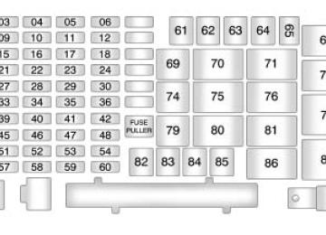
Engine Compartment Fuse Block
The engine compartment fuse block is located on the driver side of the engine compartment. See Engine Compartment Overview on page 10‑6 for more information on location.
To remove the cover, push in on the tabs at the ends of the cover and lift. To reinstall the cover, line up the tabs and push down on the cover until the tabs clicks into place. Notice: Spilling liquid on any electrical components on the vehicle may damage it. Always keep the covers on any electrical component.
10-40
Vehicle Care
Fuse
10
1112
13
14
Usage Heated Seats Grille Guard Stop Lamp (H3T Only) Roof Rack Lamps Battery Ignition Switch Front Wiper Regulated Voltage Control Power Power Locks Sunroof, Front Washer Pump Accessories (SPO) Not Used Transfer Case Control Module Radio Body Control Module
Vehicle Care
10-41
Fuse
Usage
Fuse
15
16
17
18
1920
21
22
23
2425
Rear Wiper Motor (H3 Only) Rear Wiper Pump Switch (H3 Only) Air Injection Reactor (AIR) Pump Relay/ Transmission Control Module (TCM) (V8 Only) Rear Vision Camera Cluster Rear Turn Lamp, Hazard Lamp Powertrain Control Module 1
Mass Air Flow Sensor, Canister Vent Purge Solenoid Injector/V8 Coil Fog Lamp Powertrain Control Module B26
27
2829
30
31
32
33
3435
36
37
38
Usage Transmission Control Module (TCM) Airbags Not Used Antilock Brake System, StabiliTrak® Rear Window Defogger Canister Vent Regulated Voltage Control Sensor Ignition 1
Transmission Cruise Control, Miscellaneous Horn Driver Side Rear Park Lamp Amplifier10-42
Vehicle Care
Fuse
Usage
Fuse
Usage
Fuse
Usage
39
40
41
42
43
44
45
46
47
48
49
50Daytime Running Lamps Passenger Side Headlamp Driver Side Headlamp Trailer Back-Up Lamp Front Park Lamps Air Injection Reactor (AIR) Solenoid Auxiliary Power 2/ Cigarette Lighter Electronic Throttle Control Oxygen Sensor Air Conditioning Clutch Rear Park Lamp Stop Lamp
51
52
53
54
55
56
57
58
59
60
61Auxiliary Power 1/ Cigarette Lighter StabiliTrak®, Antilock Brake System Power Heated Seat, Belt Switch Fuel System Control Module (FSCM) Trailer Parking Lamps Front Turn Signal, Hazard Signal, Courtesy Mirror Power Sunroof Transfer Case Control Module Switch Climate Controls Control Head Back‐Up Lamp Power Seats
62
63
64
67
68
82
83
84
85
91Air Injection Reactor (AIR) Pump Passenger Side Power Window Antilock Brake System, StabiliTrak® 2
Solenoid Antilock Brake System, StabiliTrak® 1 Motor Driver Side Power Window Climate Control Fan Electronic Brake Controller Trailer B+ Fuse Starter Generator MegafuseVehicle Care
10-43
Relay
Usage
Relay
Usage
Relay
Usage
66
69
70
71
72
73
74
Stop Lamp (H3T Only) Fog Lamp High, Low Beam Headlamps Rear Defogger Windshield Wiper On/Off Windshield Wiper High/Low Horn
75
76
77
78
79
80
81
Headlamp Air Conditioning Clutch Powertrain Control Module (Starter) Run, Crank Daytime Running Lamps Air Injection Reactor (AIR) Solenoid Powertrain
86
87
88
89
Back-up Ignition 3 (Heating, Ventilation, Air Conditioning) Retained Accessory Power/Accessory Park Lamp
Diode
Usage
65
90
Wiper Diode Air Conditioning Clutch Diode
10-44
Vehicle Care
Wheels and Tires
Tires Your new vehicle comes with high-quality tires made by a leading tire manufacturer. If you ever have questions about your tire warranty and where to obtain service, see your vehicle Warranty booklet for details. For additional information refer to the tire manufacturer.
{ WARNING
Poorly maintained and improperly used tires are dangerous.
. Overloading your tires can
cause overheating as a result of too much flexing. You could have an air-out and a serious accident. See Vehicle Load Limits on page 9‑27.
(Continued)
WARNING (Continued)
. Underinflated tires pose the same danger as overloaded tires. The resulting accident could cause serious injury. Check all tires frequently to maintain the recommended pressure. Tire pressure should be checked when your tires are cold. See Tire Pressure on page 10‑51.
. Overinflated tires are more likely to be cut, punctured or broken by a sudden impact — such as when you hit a pothole. Keep tires at the recommended pressure.
. Worn, old tires can cause accidents. If your tread is badly worn, or if your tires have been damaged, replace them.
Tire Sidewall Labeling Useful information about a tire is molded into the sidewall. The following illustrations are examples of a typical P‐Metric and a LT‐Metric tire sidewall.
Passenger (P‐Metric) Tire (A) Tire Size: The tire size code is a combination of letters and numbers used to define a particular tire's width, height, aspect ratio, construction type,
and service description. See the “Tire Size” illustration later in this section for more detail. (B) TPC Spec (Tire Performance Criteria Specification): Original equipment tires designed to GM's specific tire performance criteria have a TPC specification code molded onto the sidewall. GM's TPC specifications meet or exceed all federal safety guidelines. (C) DOT (Department of Transportation): The Department of Transportation (DOT) code indicates that the tire is in compliance with the U.S. Department of Transportation Motor Vehicle Safety Standards. (D) Tire Identification Number (TIN): The letters and numbers following DOT code are the Tire Identification Number (TIN).
The TIN shows the manufacturer and plant code, tire size, and date the tire was manufactured. The TIN is molded onto both sides of the tire, although only one side may have the date of manufacture. (E) Tire Ply Material: The type of cord and number of plies in the sidewall and under the tread. (F) Uniform Tire Quality Grading (UTQG): Tire manufacturers are required to grade tires based on three performance factors: treadwear, traction, and temperature resistance. For more information, see Uniform Tire Quality Grading on page 10‑61. (G) Maximum Cold Inflation Load Limit: Maximum load that can be carried and the maximum pressure needed to support that load.
Vehicle Care
10-45
For information on recommended tire pressure see Tire Pressure on page 10‑51
and Vehicle Load Limits on page 9‑27.Light Truck (LT-Metric) Tire
(A) Tire Size: The tire size code is a combination of letters and numbers used to define a particular tire's width, height, aspect ratio, construction type, and service description. See the “Tire Size” illustration later in this section for more detail.
10-46
Vehicle Care
(B) TPC Spec (Tire Performance Criteria Specification): Original equipment tires designed to GM's specific tire performance criteria have a TPC specification code molded onto the sidewall. GM's TPC specifications meet or exceed all federal safety guidelines. (C) Dual Tire Maximum Load: Maximum load that can be carried and the maximum pressure needed to support that load when used in a dual configuration. For information on recommended tire pressure see Tire Pressure on page 10‑51 and Vehicle Load Limits on page 9‑27. (D) DOT (Department of Transportation): The Department of Transportation (DOT) code indicates that the
tire is in compliance with the U.S. Department of Transportation Motor Vehicle Safety Standards. (E) Tire Identification Number (TIN): The letters and numbers following DOT code are the Tire Identification Number (TIN). The TIN shows the manufacturer and plant code, tire size, and date the tire was manufactured. The TIN is molded onto both sides of the tire, although only one side may have the date of manufacture. (F) Tire Ply Material: The type of cord and number of plies in the sidewall and under the tread. (G) Single Tire Maximum Load: Maximum load that can be carried and the maximum pressure needed to support that load when used as a single. For information on recommended
tire pressure see Tire Pressure on page 10‑51 and Vehicle Load Limits on page 9‑27.
Tire Designations
Tire Size The following examples show the different parts of a tire size.
Passenger (P‐Metric) Tire
(A) Passenger (P‐Metric) Tire: The United States version of a metric tire sizing system. The letter P as the first character in the tire size means a passenger vehicle tire engineered to standards set by the U.S. Tire and Rim Association.
(B) Tire Width: The three‐digit number indicates the tire section width in millimeters from sidewall to sidewall. (C) Aspect Ratio: A two‐digit number that indicates the tire height‐to‐width measurements. For example, if the tire size aspect ratio is 75, as shown in item C of the illustration, it would mean that the tire's sidewall is 75 percent as high as it is wide. (D) Construction Code: A letter code is used to indicate the type of ply construction in the tire. The letter R means radial ply construction; the letter D means diagonal or bias ply construction; and the letter B means belted‐bias ply construction. (E) Rim Diameter: Diameter of the wheel in inches.
(F) Service Description: These characters represent the load index and speed rating of the tire. The load index represents the load carry capacity a tire is certified to carry. The speed rating is the maximum speed a tire is certified to carry a load.
Light Truck (LT‐Metric) Tire
(A) Light Truck (LT‐Metric) Tire: The United States version of a metric tire sizing system. The letters LT as the first two characters in the tire size means a light truck tire engineered to standards set by the U.S. Tire and Rim Association.
Vehicle Care
10-47
(B) Tire Width: The three‐digit number indicates the tire section width in millimeters from sidewall to sidewall. (C) Aspect Ratio: A two‐digit number that indicates the tire height‐to‐width measurements. For example, if the tire size aspect ratio is 75, as shown in item C of the light truck (LT‐Metric) tire illustration, it would mean that the tire's sidewall is 75 percent as high as it is wide. (D) Construction Code: A letter code is used to indicate the type of ply construction in the tire. The letter R means radial ply construction; the letter D means diagonal or bias ply construction; and the letter B means belted‐bias ply construction.
10-48
Vehicle Care
(E) Rim Diameter: Diameter of the wheel in inches. (F) Load Range: Load Range. (G) Service Description: The service description indicates the load index and speed rating of a tire. If two numbers are given as in the example, 120/116, then this represents the load index for single versus dual wheel usage (single/dual). The speed rating is the maximum speed a tire is certified to carry a load.
Tire Terminology and Definitions Air Pressure: The amount of air inside the tire pressing outward on each square inch of the tire. Air pressure is expressed in psi (pounds per square inch) or kPa (kilopascal).
Accessory Weight: This means the combined weight of optional accessories. Some examples of optional accessories are, automatic transmission, power steering, power brakes, power windows, power seats, and air conditioning. Aspect Ratio: The relationship of a tire's height to its width. Belt: A rubber coated layer of cords that is located between the plies and the tread. Cords may be made from steel or other reinforcing materials. Bead: The tire bead contains steel wires wrapped by steel cords that hold the tire onto the rim.
Bias Ply Tire: A pneumatic tire in which the plies are laid at alternate angles less than 90 degrees to the centerline of the tread. Cold Tire Pressure: The amount of air pressure in a tire, measured in psi (pounds per square inch) or kPa (kilopascal) before a tire has built up heat from driving. See Tire Pressure on page 10‑51. Curb Weight: The weight of a motor vehicle with standard and optional equipment including the maximum capacity of fuel, oil, and coolant, but without passengers and cargo.
DOT Markings: A code molded into the sidewall of a tire signifying that the tire is in compliance with the U.S. Department of Transportation (DOT) motor vehicle safety standards. The DOT code includes the Tire Identification Number (TIN), an alphanumeric designator which can also identify the tire manufacturer, production plant, brand, and date of production. GVWR: Gross Vehicle Weight Rating. See Vehicle Load Limits on page 9‑27. GAWR FRT: Gross Axle Weight Rating for the front axle. See Vehicle Load Limits on page 9‑27. GAWR RR: Gross Axle Weight Rating for the rear axle. See Vehicle Load Limits on page 9‑27.
Intended Outboard Sidewall: The side of an asymmetrical tire, that must always face outward when mounted on a vehicle. Kilopascal (kPa): The metric unit for air pressure. Light Truck (LT‐Metric) Tire: A tire used on light duty trucks and some multipurpose passenger vehicles. Load Index: An assigned number ranging from 1 to 279
that corresponds to the load carrying capacity of a tire. Maximum Inflation Pressure: The maximum air pressure to which a cold tire can be inflated. The maximum air pressure is molded onto the sidewall. Maximum Load Rating: The load rating for a tire at the maximum permissible inflation pressure for that tire.Vehicle Care
10-49
Maximum Loaded Vehicle Weight: The sum of curb weight, accessory weight, vehicle capacity weight, and production options weight. Normal Occupant Weight: The number of occupants a vehicle is designed to seat multiplied by 68 kg (150 lbs). See Vehicle Load Limits on page 9‑27. Occupant Distribution: Designated seating positions. Outward Facing Sidewall: The side of an asymmetrical tire that has a particular side that faces outward when mounted on a vehicle. The side of the tire that contains a whitewall, bears white lettering, or bears manufacturer, brand, and/or model name molding that is higher or deeper than the same moldings on the other sidewall of the tire.
10-50
Vehicle Care
Passenger (P-Metric) Tire: A tire used on passenger cars and some light duty trucks and multipurpose vehicles. Recommended Inflation Pressure: Vehicle manufacturer's recommended tire inflation pressure as shown on the tire placard. See Tire Pressure on page 10‑51 and Vehicle Load Limits on page 9‑27. Radial Ply Tire: A pneumatic tire in which the ply cords that extend to the beads are laid at