- Download PDF Manual
-
link another RKE transmitter to memory. NOTE: A chime sound may be heard if Setting Memory was inhibited for any reason. Memory Position Recall NOTE: • The vehicle must be in PARK to recall memory posi-
tions.
• Not all motors may be moved at one time. Refer to the “Seats/Eight-Way Power Seat” in this section for fur- ther information.
To recall the memory settings for driver one, press MEMORY button number 1 on the driver’s seat or the UNLOCK button on the RKE transmitter linked to memory position 1. To recall the memory setting for driver two, press MEMORY button number 2 on the driver’s seat or the UNLOCK button on the RKE transmitter linked to memory position 2. A recall can be cancelled by pressing any of the MEMORY buttons on the driver’s seat during a recall (S, 1, or 2), or pressing any one of the power seat buttons, pressing the adjustable pedals button, or pressing either the LOCK or UNLOCK button on the RKE transmitter
UNDERSTANDING THE FEATURES OF YOUR VEHICLE 111
when not in the ignition switch. When a recall is can- celled, the driver’s seat and the pedals stop moving. A delay of one second will occur before another recall can be selected. NOTE: A chime sound may be heard if setting memory was inhibited for any reason. To Disable a RKE Transmitter Linked to Memory1. Turn the ignition switch to the OFF position and remove the key. 2. Press and release the memory SET button located on the driver’s seat. 3. Within 10 seconds, press and release the UNLOCK button on the RKE transmitter. To disable another RKE transmitter linked to either memory position, repeat Steps 1-3 for each RKE trans- mitter.
112 UNDERSTANDING THE FEATURES OF YOUR VEHICLE NOTE: The capability to link RKE transmitters to memory is enabled when delivered from the factory. The capability to link RKE transmitters to memory can be disabled (or later re-enabled) by an authorized dealer. For vehicles equipped with the Electronic vehicle Informa- tion Center (EVIC), refer to “Electronic Vehicle Informa- tion Center (EVIC)/Customer-Programmable Features” in “Understanding Your Instrument Panel” for further information. Self-Limiting Control The memory system includes a self-limiting control for full travel positioning of power seat and adjustable pedal movement (all directions). This self-limiting control may, however, develop an unintended movement limitation if an obstruction is encountered sometime during usage. One example of such an occurrence may include a box or package obstructing the full rearward movement of the driver’s seat. Once the obstruction is removed, the self- limiting control may store a new maximum position. the
self-limiting control may be reset by reaching the new stored position, then press and release MEMORY button 1 or 2. Continued seat travel beyond the new stored position will indicate the self-limiting control has been reset. Driver Easy Exit and Easy Entry Control This additional feature provides automatic driver’s seat positioning which will enhance driver mobility into and out of the vehicle. The seat cushion will move rearward approximately 2.5 in (60 mm) when the key is removed from the ignition switch. The seat will move forward approximately 2.5 in (60 mm) when the key is placed into the ignition and turned out of the LOCK position. Each stored memory setting will have an associated Easy Exit and Easy Entry position. The Easy Exit and Easy Entry feature may be automatically disabled if the seat is positioned rearward enough and there is no benefit in moving the seat any farther rearward.
NOTE: The Easy Entry/Easy Exit feature can be en- abled or disabled through the programmable features in the Electronic Vehicle Information Center (EVIC). Refer to “Electronic Vehicle Information Center (EVIC)/ Customer-Programmable Features” in “Understanding Your Instrument Panel” for further information.
TO OPEN AND CLOSE THE HOOD To open the hood, two latches must be released. 1. Pull the hood release lever located below the steering wheel at the base of the instrument panel.
UNDERSTANDING THE FEATURES OF YOUR VEHICLE 113
Hood Release
114 UNDERSTANDING THE FEATURES OF YOUR VEHICLE 2. Reach into the opening beneath the center of the hood and push the safety latch lever from right to left to release it, before raising the hood.
Safety Latch (1500 Series Shown)
CAUTION!
To prevent possible damage, do not slam the hood to close it. Use a firm downward push at the front center of the hood to ensure that both latches engage.
WARNING!
Be sure the hood is fully latched before driving your vehicle. If the hood is not fully latched, it could open when the vehicle is in motion and block your vision. Failure to follow this warning could result in serious injury or death.
LIGHTS The headlight switch is located on the left side of the instrument panel, next to the steering wheel. The head- light switch controls the operation of the headlights, parking lights, instrument panel lights, cargo lights and fog lights (if equipped).
UNDERSTANDING THE FEATURES OF YOUR VEHICLE 115
Your vehicle is equipped with plastic headlight and fog light (if equipped) lenses that are lighter and less suscep- tible to stone breakage than glass lights. Plastic is not as scratch resistant as glass and therefore different lens cleaning procedures must be followed. To minimize the possibility of scratching the lenses and reducing light output, avoid wiping with a dry cloth. To remove road dirt, wash with a mild soap solution fol- lowed by rinsing.CAUTION!
Do not use abrasive cleaning components, solvents, steel wool or other abrasive materials to clean the lenses.
Headlight Switch Location
116 UNDERSTANDING THE FEATURES OF YOUR VEHICLE Headlights
To turn on the headlights, rotate the headlight switch clockwise. When the headlight switch is on the parking lights, taillights, license plate light and instrument panel lights are also turned on. To turn off the headlights, rotate the headlight switch back to the O (Off) position. Automatic Headlights — If Equipped This system automatically turns the headlights on or off according to ambient light levels. To turn the system on, rotate the headlight switch to the A (AUTO) position.
Automatic Headlight Position
When the system is on, the Headlight Delay feature is also on. This means the headlights will stay on for up to 90 seconds after you turn the ignition switch to the OFF position. To turn the automatic headlights off, turn the headlight switch out of the AUTO position.
NOTE: The engine must be running before the head- lights will turn on in the Automatic Mode. SmartBeam™ — If Equipped The SmartBeam™ system provides increased forward lighting at night by automating high beam control through the use of a digital camera mounted on the inside rearview mirror. This camera detects vehicle spe- cific light and automatically switches from high beams to low beams until the approaching vehicle is out of view. If the windshield or SmartBeam™ mirror is re- NOTE: placed, the SmartBeam™ mirror must be re-aimed to ensure proper performance. See your local authorized dealer. To Activate 1. Enable the Automatic High Beams. Refer to “Elec- tronic Vehicle Information Center (EVIC)/Customer- Programmable Features” in “Understanding Your Instru- ment Panel” for further information.
UNDERSTANDING THE FEATURES OF YOUR VEHICLE 117
2. Turn the headlight switch to the AUTO headlight position. 3. Push the multifunction lever away from you (toward front of vehicle) to engage the high beam mode. NOTE: This system will not activate until the vehicle is at or above 20 mph (32 km/h). To Deactivate 1. Pull back on the multifunction lever to manually deactivate the system (normal operation of low beams). 2. Push back on the multifunction lever once again to reactivate the system. NOTE: Broken, muddy, or obstructed headlights and taillights of vehicles in the field of view will cause headlights to remain on longer (closer to the vehicle). Also, dirt, film and other obstructions (sticker, toll box, etc.) on the windshield or camera lens will cause the system to function improperly.118 UNDERSTANDING THE FEATURES OF YOUR VEHICLE Headlight Delay To aid in your exit, your vehicle is equipped with a headlight delay that will leave the headlights on for approximately 90 seconds. This delay is initiated when the ignition is turned OFF while the headlight switch is on, and then the headlight switch is cycled off. Headlight delay can be cancelled by either turning the headlight switch on then off, or by turning the ignition ON. The headlight delay time is programmable on vehicles equipped with an Electronic Vehicle Information Center (EVIC). Refer to “Electronic Vehicle Information Center (EVIC)/Customer-Programmable Features (SETUP)” in “Understanding Your Instrument Panel” for further information. Parking Lights and Panel Lights
To turn on the parking lights and instrument panel lights, rotate the headlight switch clockwise to the
parking light symbol. To turn off the parking lights, rotate the headlight switch back to the O (Off) position. Fog Lights — If Equipped The fog lights are turned on by rotating the headlight switch to the parking light or headlight position and pushing in the headlight rotary control.
Fog Light Switch
The fog lights will operate only when the parking lights are on or when the vehicle headlights are on low beam. An indicator light located in the instrument cluster will illuminate when the fog lights are on. The fog lights will turn off when the switch is pushed a second time, when the headlight switch is rotated to the off position, or the high beam is selected. Interior Lights Courtesy and dome lights are turned on when the front doors are opened, when the dimmer control (rotating wheel on the bottom of the switch) is rotated to the far right detent position, or if equipped, when the UNLOCK button is pressed on the Remote Keyless Entry (RKE) transmitter. When a door is open and the interior lights are on, rotating the dimmer control all the way left, to the OFF detent, will cause all the interior lights to go out. This is also known as the ⬙Party⬙ mode because it allows the doors to stay open for extended periods of time without discharging the vehicle’s battery.
UNDERSTANDING THE FEATURES OF YOUR VEHICLE 119
The brightness of the instrument panel lighting can be regulated by rotating the dimmer control right (brighter) or left (dimmer). When the headlights are on you can supplement the brightness of the odometer, trip odom- eter, radio and overhead console by rotating the control to the right until you hear a click. This feature is termed the “Parade” mode and is useful when headlights are required during the day.Dimmer Control
120 UNDERSTANDING THE FEATURES OF YOUR VEHICLE Cargo Light The cargo lights are turned on by pressing on the cargo button.
Cargo Light Switch
The cargo lights will also turn on for approximately 30 seconds when a RKE transmitter UNLOCK button is pressed, as part of the Illuminated Entry feature.
Lights-on Reminder If the headlights, parking lights, or cargo lights are left on after the ignition is turned OFF, a chime will sound when the driver’s door is opened. Battery Saver To protect the life of your vehicle’s battery, load shedding is provided for both the interior and exterior lights. If the ignition is OFF and any door is left ajar for 10 minutes or the dimmer control is rotated right for 10 minutes, the interior lights will automatically turn off. If the headlights remain on while the ignition is cycled OFF, the exterior lights will automatically turn off after eight minutes. If the headlights are turned on and left on for eight minutes while the ignition is OFF, the exterior lights will automatically turn off. NOTE: Battery saver mode is cancelled if the ignition is ON.
Daytime Running Lights (DRL) (Canada Only and Fleet Vehicles) The headlights on your vehicle will illuminate when the engine is started and the transmission is in any gear except PARK. This provides a constant ⬙Lights ON⬙ condition until the ignition is turned OFF. The lights illuminate at less than 50% of normal intensity. If the parking brake is applied, the Daytime Running Lights (DRL) will turn OFF. Also, if a turn signal is activated, the DRL lamp on the same side of the vehicle will turn off for the duration of the turn signal activation. Once the turn signal is no longer active, the DRL lamp will illuminate. Multifunction Lever The multifunction lever is located on the left side of the steering column.
UNDERSTANDING THE FEATURES OF YOUR VEHICLE 121
Turn Signals Move the multifunction lever up or down and the arrows on each side of the instrument cluster flash to show proper operation of the front and rear turn signal lights.
Turn Signal Lever
that
it would suggest
122 UNDERSTANDING THE FEATURES OF YOUR VEHICLE If either light remains on and does not flash, or NOTE: there is a very fast flash rate, check for a defective outside light bulb. If an indicator fails to light when the lever is moved, the indicator bulb is defective. Lane Change Assist Tap the lever up or down once, without moving beyond the detent, and the turn signal (right or left) will flash three times then automatically turn off. Flash-To-Pass You can signal another vehicle with your headlights by partially pulling the multifunction lever toward the steer- ing wheel. This will cause the high beam headlights to turn on until the lever is released.
High/Low Beam Switch Push the multifunction lever toward the instrument panel to switch the headlights to high beam. Pulling the multifunction back toward the steering wheel will turn the low beams back on, or shut the high beams off.
High/Low Beam Switch
WINDSHIELD WIPERS AND WASHERS
Windshield Wipers The wipers and washers are operated by a switch in the multifunction lever. Turn the end of the handle to select the desired wiper speed.
UNDERSTANDING THE FEATURES OF YOUR VEHICLE 123
Intermittent Wiper System The intermittent feature of this system was designed for use when weather conditions make a single wiping cycle, with a variable pause between cycles, desirable. For maximum delay between cycles, rotate the control knob into the upper end of the delay range. The delay interval decreases as you rotate the knob until it enters the low continual speed position. The delay can be regulated from a maximum of about 18 seconds between cycles, to a cycle every two seconds. The delay intervals will double in duration when the vehicle speed is 10 mph (16 km/h) or less.
Windshield Wiper/Washer Switch
124 UNDERSTANDING THE FEATURES OF YOUR VEHICLE Windshield Washers To use the windshield washer, push the washer knob, located on the end of the multifunction lever, inward to the second detent. Washer fluid will be sprayed until the washer knob is released from this position. If the washer knob is depressed while in the delay range, the wiper will operate for several seconds after the washer knob is released. It will then resume the intermittent interval previously selected. If the washer knob is pushed for a period greater than one second while in the off position, the wiper will cycle approximately three times after the wash knob is released. To prevent freeze-up of your windshield washer system in cold weather, select a solution or mixture that meets or exceeds the temperature range of your climate. This rating information can be found on most washer fluid containers.
WARNING!
Sudden loss of visibility through the windshield could lead to an accident. You might not see other vehicles or other obstacles. To avoid sudden icing of the windshield during freezing weather, warm the windshield with the defroster before and during windshield washer use.
Mist Feature Push the washer knob, located on the end of the multi- function lever, inward to the first detent. The wipers will cycle one time and automatically shut off to clear road mist or spray from a passing vehicle.
TILT STEERING COLUMN the steering column This feature allows you to tilt upward or downward. The tilt lever is located on the steering column, below the multifunction lever.
Pull the lever toward the steering wheel to unlock the steering column. With one hand firmly on the steering wheel, move the steering column up or down, as desired. Release the lever to lock the steering column firmly in place.
Tilt Steering Lever
UNDERSTANDING THE FEATURES OF YOUR VEHICLE 125
WARNING!
Do not adjust the steering column while driving. Adjusting the steering column while driving or driv- ing with the steering column unlocked, could cause the driver to lose control of the vehicle. Be sure the steering column is locked before driving your ve- hicle. Failure to follow this warning may result in serious injury or death.
HEATED STEERING WHEEL — IF EQUIPPED The steering wheel contains a heating element that helps warm your hands in cold weather. The heated steering wheel has only one temperature setting. Once the heated steering wheel has been turned on it will operate for approximately 58 to 70 minutes before automatically shutting off. The heated steering wheel can shut off early or may not turn on when the steering wheel is already warm.
126 UNDERSTANDING THE FEATURES OF YOUR VEHICLE The heated steering wheel switch is located on the switch bank below the climate controls.
Press the switch to turn on the heated steering wheel. The light on the switch will illuminate to indicate the steering wheel heater is on. Pressing the switch a second time will turn off the heated steering wheel and light indicator.
wheel to operate.
NOTE: • The engine must be running for the heated steering • The heated steering wheel can be programmed to come on during a remote start. Refer to “Remote Starting System — If Equipped” in Section 4 for further information.
WARNING!
• Persons who are unable to feel pain to the skin because of advanced age, chronic illness, diabetes, spinal cord injury, medication, alcohol use, ex- haustion, or other physical conditions must exer- cise care when using the steering wheel heater. It may cause burns even at low temperatures, espe- cially if used for long periods. • Do not place anything on the steering wheel that insulates against heat, such as a blanket or cush- ion. This may cause the steering wheel heater to overheat.
DRIVER ADJUSTABLE PEDALS — IF EQUIPPED The power adjustable accelerator and brake pedals allow the driver to establish a comfortable position relative to the steering wheel and pedals. Adjustment
1. Position the driver’s seat so that you are at least 10 in (25.4 cm) away from the airbag, located in the center of the steering wheel. 2. Fasten and adjust the seatbelts. 3. Move the adjustable pedal switch, located to the left side of the steering column, in the direction you desire the pedals to move.
UNDERSTANDING THE FEATURES OF YOUR VEHICLE 127
Adjustable Pedals Switch
NOTE: The pedals cannot be adjusted when the vehicle is in REVERSE or when the Electronic Speed Control is set.
ELECTRONIC SPEED CONTROL — IF EQUIPPED When engaged, Electronic Speed Control takes over the accelerator operation at speeds greater than 25 mph (40 km/h). The Electronic Speed Control lever is located on the right side of the steering wheel.
128 UNDERSTANDING THE FEATURES OF YOUR VEHICLE
CAUTION!
Do not place any article under the adjustable pedals or impede its ability to move as it may cause damage to the pedal controls. Pedal travel may become lim- ited if movement is stopped by an obstruction in the adjustable pedal’s path.
WARNING!
Do not adjust the pedals while the vehicle is moving. You could lose control and have an accident. Always adjust the pedals while the vehicle is parked.
Electronic Speed Control Lever
In order to ensure proper operation, the Elec- NOTE: tronic Speed Control System has been designed to shut down if multiple Speed Control functions are operated simultaneously. If this occurs, the Electronic Speed Con- trol System can be reactivated by pushing the Electronic Speed Control ON/OFF button and resetting the desired vehicle set speed. To Activate Push the ON/OFF button (located in the end of the lever) once and the cruise indicator light (located in the mes- sage window of the cluster) will illuminate showing that the Electronic Speed Control system is on. To turn the Electronic Speed Control system off, push the ON/OFF button a second time and both the Electronic Speed Control system and indicator will turn off.
UNDERSTANDING THE FEATURES OF YOUR VEHICLE 129
WARNING!
Leaving the Electronic Speed Control system on when not in use is dangerous. You could accidently set the system or cause it to go faster than you want. You could lose control and have an accident. Always leave the Electronic Speed Control system off when you are not using it.
To Set a Desired Speed When the vehicle has reached the desired speed, press the SET lever downward and then release. Lift your foot off the accelerator and the vehicle will operate at the selected speed.
130 UNDERSTANDING THE FEATURES OF YOUR VEHICLE Deactivating Electronic Speed Control A soft tap on the brake pedal or pulling the Electronic Speed Control lever (CANCEL) toward you will deacti- vate the Electronic Speed Control without erasing the set speed memory. Pushing the ON/OFF button to the OFF position or turning OFF the ignition erases the set speed memory. To Resume Speed To resume a previously set speed, raise the Electronic Speed Control lever (RESUME ACCEL) upwards and release. Resume can be used at any speed above 30 mph (50 km/h). Varying The Speed Setting When the Electronic Speed Control is set, you can in- crease speed by pushing up and holding the RESUME ACCEL lever. If the lever is continually held in the
RESUME ACCEL position, the set speed will continue to increase until the lever is released, then the new set speed will be established. lever RESUME Raising the Electronic Speed Control ACCEL upwards once will result in a 1 mph (1 km/h) speed increase. Each time the lever is tapped upward speed increases, so tapping the lever three times will increase speed by 3 mph (5 km/h), etc. To decrease speed while the Electronic Speed Control is set, push down and hold the SET DECEL lever. If the lever is continually held in the SET DECEL position, the set speed will continue to decrease until the lever is released. Release the lever when the desired speed is reached, and the new set speed will be established. Tapping the Electronic Speed Control lever SET DECEL downward once will result in a 1 mph (1 km/h) speed decrease. Each time the lever is tapped downward, speed decreases.
To Accelerate for Passing Press the accelerator as you would normally. When the pedal is released, the vehicle will return to the set speed. NOTE: The Electronic Speed Control system maintains speed up and down hills. A slight speed change on moderate hills is normal. Your vehicle may experience a downshift (automatic transmissions only) while climbing uphill or descending downhill. This downshift is necessary to maintain vehicle set speed. On steep hills a greater speed loss or gain may occur so it may be preferable to drive without Electronic Speed Control.
UNDERSTANDING THE FEATURES OF YOUR VEHICLE 131
WARNING!
Electronic Speed Control can be dangerous where the system cannot maintain a constant speed. Your ve- hicle could go too fast for the conditions, and you could lose control. An accident could be the result. Do not use Electronic Speed Control in heavy traffic or on roads that are winding, icy, snow-covered or slippery.
132 UNDERSTANDING THE FEATURES OF YOUR VEHICLE PARKSENSE姞 REAR PARK ASSIST — IF EQUIPPED The ParkSense威 Rear Park Assist system provides visual and audible indications of the distance between the rear bumper and the detected obstacle when backing up. Refer to ParkSense威 System Usage and Precautions for limitations of this system and recommendations. ParkSense威 will remember the last system state (enabled or disabled) from the last ignition cycle when the ignition is changed to the RUN/ON position. ParkSense威 can be active only when the shift lever is in REVERSE. If ParkSense威 is enabled at this shift lever position, the system will be active until the vehicle speed is increased to approximately 11 mph (18 km/h) or above. The system will be active again if the vehicle speed is decreased to speeds less than approximately 10 mph (16 km/h).
ParkSense姞 Sensors The four ParkSense威 sensors, located in the rear bumper, monitor the area behind the vehicle that is within the sensors’ field of view. The sensors can detect obstacles from approximately 12 in (30 cm) up to 79 in (200 cm) from the rear bumper in the horizontal direction, depending on the location, type and orientation of the obstacle. ParkSense姞 Warning Display The ParkSense威 Warning screen will only be displayed if Sound and Display is selected from the Customer- Programmable Features section of the Electronic Vehicle Information Center (EVIC). Refer to “Electronic Vehicle Information Center (EVIC)/Personal Settings (Customer- Programmable Features) (SETUP)” in “Understanding Your Instrument Panel” for further information.
The ParkSense威 Warning Display is located in the instru- ment cluster’s EVIC display. It provides both visual and audible warnings to indicate the distance between the rear bumper and the detected obstacle.
UNDERSTANDING THE FEATURES OF YOUR VEHICLE 133
When the vehicle is in REVERSE, the warning display will turn ON indicating the system status.Rear ParkSense威 Display
Rear Park Assist On
134 UNDERSTANDING THE FEATURES OF YOUR VEHICLE
Rear Park Assist Disabled
ParkSense威 will indicate a detected obstacle by showing three solid arcs and will produce a 1⁄2 second tone. As the vehicle moves closer to the object the EVIC display will show fewer arcs and the sound tone will change from slow, to fast, to continuous.
Slow Tone
UNDERSTANDING THE FEATURES OF YOUR VEHICLE 135
Fast Tone
Continuous Tone
The vehicle is close to the obstacle when the EVIC display shows one flashing arc and sounds a continuous tone.
136 UNDERSTANDING THE FEATURES OF YOUR VEHICLE WARNING DISPLAY DISTANCES
DISPLAY MESSAGE
OBSTACLE DISTANCE FROM:
ARC’s
REAR CORNERS
REAR CENTER
Park Assist ON
Warning Object Detected Warning Object Detected Warning Object Detected Warning Object Detected Warning Object Detected Warning Object Detected Warning Object Detected
27.5 in (70 cm) 25.5 in (65 cm) 19.7 in (50 cm) 15.7 in (40 cm) 11.8 in (30 cm)
78.7 in (200 cm) 39.3 in (100 cm) 31.4 in (80 cm) 25.5 in (65 cm) 19.7 in (50 cm) 15.7 in (40 cm) 11.8 in (30 cm)
None 3 Solid
3 Flashing 3 Flashing 2 Flashing 2 Flashing 2 Flashing 1 Flashing
AUDIBLE SIG-
NAL None
Yes, 1/2 second
Slow Tone Slow Tone Fast Tone Fast Tone Fast Tone
Continuous Tone
NOTE: ParkSense威 will MUTE the radio, if on, when the system is sounding an audio tone.
Enable/Disable ParkSense姞 ParkSense威 can be enabled and disabled with a switch located in the switch bank of the instrument panel or through the Customer-Programmable Features section of the EVIC. The available choices are: OFF, Sound Only, or Sound and Display. Refer to “Electronic Vehicle Informa- tion Center (Customer- Programmable Features (SETUP)” in “Understanding Your Instrument Panel” for further information.
(EVIC)/Personal
Settings
UNDERSTANDING THE FEATURES OF YOUR VEHICLE 137
Park Assist Switch
When the switch is pressed to disable the system, the instrument cluster will display the “PARK ASSIST DIS- ABLED” message for approximately five seconds. Refer to “Electronic Vehicle Information Center (EVIC)” in “Understanding Your Instrument Panel” for further in- formation. When the shift lever is moved to REVERSE
138 UNDERSTANDING THE FEATURES OF YOUR VEHICLE and the system is disabled, the EVIC will display the “PARK ASSIST DISABLED” message for as long as the vehicle is in REVERSE. The switch LED will be ON when ParkSense威 is disabled or defective. The switch LED will be OFF when Park- Sense威 is enabled. Service ParkSense姞 When the ParkSense威 Rear Park Assist system is mal- functioning, the instrument cluster will actuate a single chime, once per ignition cycle, and it will display the “CLEAN PARK ASSIST SENSORS” message. Refer to “Electronic Vehicle Information Center (EVIC)” in “Un- derstanding Your Instrument Panel” for further informa- tion. When the shift lever is moved to REVERSE and the system has detected a faulted condition, the EVIC will display the “CLEAN PARK ASSIST SENSORS” message for as long as the vehicle is in REVERSE. Under this condition ParkSense威 will not operate.
If “CLEAN PARK ASSIST SENSORS” appears in the Electronic Vehicle Information Center (EVIC) after mak- ing sure the rear bumper is clean and free of snow, ice, mud, or other debris, see your authorized dealer. Cleaning ParkSense姞 Clean the ParkSense威 sensors with water, car wash soap and a soft cloth. Do not use rough or hard cloths. Do not scratch or poke the sensors. Otherwise, you could dam- age the sensors. ParkSense姞 System Usage and Precautions NOTE: • Ensure that the rear bumper is free of dirt and debris to keep the ParkSense威 Rear Park Assist system oper- ating properly. • Jackhammers, large trucks, and other vibrations could affect the performance of the ParkSense威 Rear Park Assist system.
• When you turn ParkSense威 off, the instrument cluster will display “PARK ASSIST DISABLED.” Further- more, once you turn ParkSense威 off, it remains off until you turn it on again, even if you cycle the ignition key. • When you move the shift lever to the REVERSE position and ParkSense威 is turned off, the instrument cluster will display “PARK ASSIST DISABLED” mes- sage for as long as the vehicle is in reverse. • ParkSense威, when on, will MUTE the radio when it is • If a ParkSense威 system malfunction occurs, a single chime will sound once per ignition cycle. In addition, the Electronic Vehicle Information Center (EVIC) will display “CLEAN PARK ASSIST SENSORS” and the LED in the ParkSense威 switch will illuminate. If this message continues to appear in the Electronic Vehicle
sounding a tone.
UNDERSTANDING THE FEATURES OF YOUR VEHICLE 139
Information Center (EVIC) after making sure the rear bumper is clean and free of snow, ice, mud, or other debris, see your authorized dealer. • Clean the ParkSense威 sensors regularly, taking care not to scratch or damage them. The sensors must not be covered with ice, snow, slush, mud, dirt, or debris. Failure to do so can result in the system not working properly. The ParkSense威 system might not detect an obstacle behind the bumper, or it could provide a false indication that an obstacle is behind the bumper. • Objects must not be within 12 in (30 cm) from the rear bumper while driving the vehicle. Failure to do so can result in the system misinterpreting a close object as a sensor problem, causing the “CLEAN PARK ASSIST SENSORS” message to be displayed in the instrument cluster.140 UNDERSTANDING THE FEATURES OF YOUR VEHICLE
CAUTION!
• The ParkSense威 Rear Park Assist system is only a parking aid and it is unable to recognize every obstacle, including small obstacles. Parking curbs might be temporarily detected or not detected at all. Obstacles located above or below the Park- Sense威 sensors will not be detected when they are in close proximity. • The vehicle must be driven slowly when using the ParkSense威 Rear Park Assist system to be able to stop in time when the obstacle is detected. It is recommended that the driver looks over his/her shoulder when using ParkSense威.
WARNING!
• Drivers must be careful when backing up even when using the ParkSense威 Rear Park Assist sys- tem. Always check carefully behind your vehicle, look behind you, and be sure to check for pedes- trians, animals, other vehicles, obstructions, and blind spots before backing up. You are responsible for safety and must continue to pay attention to your surroundings. Failure to do so can result in serious injury or death.
(Continued)
WARNING! (Continued)
• Before using the ParkSense威 Rear Park Assist system, it is strongly recommended that the ball mount and hitch ball assembly is disconnected from the vehicle when the vehicle is not used for towing. Failure to do so can result in injury or damage to vehicles or obstacles because the hitch ball will be much closer to the obstacle than the rear bumper when the warning display turns on the single flashing arc and sounds the continuous tone. Also, the ParkSense威 sensors could detect the ball mount and hitch ball assembly, depending on its size and shape, giving a false indication that an obstacle is behind the vehicle.
UNDERSTANDING THE FEATURES OF YOUR VEHICLE 141
PARKVIEW姞 REAR BACK UP CAMERA — IF EQUIPPED Your vehicle may be equipped with the ParkView威 Rear Back Up Camera that allows you to see an on-screen image of the rear of your vehicle whenever the shift lever is put into REVERSE. The image will be displayed on the Navigation/Multimedia radio display screen. The Park- View威 camera is located next to the tailgate handle on the rear of the vehicle.
WARNING!
Drivers must be careful when backing up even when using the ParkView威 Rear Back Up Camera. Always check carefully behind your vehicle, and be sure to check for pedestrians, animals, other vehicles, ob- structions, or blind spots before backing up. You are responsible for the safety of your surroundings and must continue to pay attention while backing up. Failure to do so can result in serious injury or death.
142 UNDERSTANDING THE FEATURES OF YOUR VEHICLE
CAUTION!
• To avoid vehicle damage, ParkView威 should only be used as a parking aid. The ParkView威 camera is unable to view every obstacle or object in your drive path. • To avoid vehicle damage, the vehicle must be driven slowly when using ParkView威 to be able to stop in time when an obstacle is seen. It is recom- mended that the driver look frequently over his/ her shoulder when using ParkView威.
If snow, ice, mud, or anything else builds up on NOTE: the camera lens, clean the lens, rinse with water, and dry with a soft cloth. Do not cover the lens.
Turning ParkView姞 On or Off — With Navigation/Multimedia Radio
1. Press the “menu” hard key. 2. Select “system setup” soft key. 3. Press the “camera setup” soft key. 4. Enable or disable the rear camera feature by selecting “enable rear camera in reverse” soft key. 5. Press the “save” soft key. 6. When the vehicle is shifted into REVERSE, an image of the rear of the vehicle will appear with a caution note to “check entire surroundings” displayed across the top of the screen. After five seconds this note will disappear. 7. When the vehicle is shifted out of REVERSE, the rear camera mode is exited and the navigation or audio screen appears again.
Turning ParkView姞 On or Off — Without Navigation/Multimedia Radio
1. Press the “menu” hard key. 2. Select “system setup” soft key. 3. Enable or disable the rear camera feature by selecting “enable rear camera in reverse” soft key. 4. When the vehicle is shifted into REVERSE, an image of the rear of the vehicle will appear with a caution note to “check entire surroundings” displayed across the top of the screen. After five seconds this note will disappear. 5. When the vehicle is shifted out of REVERSE, the rear camera mode is exited and the audio screen appears again.
OVERHEAD CONSOLE — IF EQUIPPED The overhead console is located on the headliner above the review mirror. The overhead console contains the following features:
UNDERSTANDING THE FEATURES OF YOUR VEHICLE 143
• Courtesy/Reading Lights • Power Sunroof Switch — If Equipped • Power Sliding Rear Window Switch — If Equipped • Universal Garage Door Opener — If Equipped
Overhead Console
144 UNDERSTANDING THE FEATURES OF YOUR VEHICLE Courtesy/Reading Lights Both lights in the overhead console and rear passenger compartment will illuminate as courtesy lights when a door is opened, when the dimmer control is rotated to the courtesy light position (full right position), or when the UNLOCK button is pressed on the Remote Keyless Entry (RKE) transmitter, if equipped. These lights are also operated individually as reading lights by pressing on the corresponding lens.
Front Courtesy/Reading Lights
UNDERSTANDING THE FEATURES OF YOUR VEHICLE 145
NOTE: The courtesy/reading lights will remain on until the switch is pressed a second time, so be sure they have been turned off before leaving the vehicle. If the interior lights are left on after the ignition is turned OFF, they will extinguish after 15 minutes.GARAGE DOOR OPENER — IF EQUIPPED HomeLink威 replaces up to three remote controls (hand- held transmitters) that operate devices such as garage door openers, motorized gates, lighting or home security systems. The HomeLink威 unit operates off your vehicle’s battery.
Rear Passenger Courtesy/Reading Light
146 UNDERSTANDING THE FEATURES OF YOUR VEHICLE The HomeLink威 buttons are located in the overhead console, and contain one, two or three dots/lines desig- nating the different HomeLink威 channels.
HomeLink威 Buttons
NOTE: HomeLink威 is disabled when the Vehicle Secu- rity Alarm is active.
WARNING!
• Your motorized door or gate will open and close while you are training the Universal Transceiver. Do not train the transceiver if people, pets or other objects are in the path of the door or gate. Only use this transceiver with a garage door opener that has a “stop and reverse” feature as required by federal safety standards. This includes most garage door opener models manufactured after 1982. Do not use a garage door opener without these safety features. Call toll-free 1–800–355–3515 or, on the Internet at www.HomeLink.com for safety infor- mation or assistance. • Vehicle exhaust contains carbon monoxide, a dan- gerous gas. Do not run your vehicle in the garage while training the transceiver. Exhaust gas can cause serious injury or death.
Programming HomeLink姞
Before You Begin If you have not trained any of the HomeLink威 buttons, erase all channels before you begin training. To do this, press and hold the two outside buttons for 20 seconds. The EVIC will display “CLEARING CHAN- NELS”. Release the buttons when the EVIC message states “CHANNELS CLEARED”. It is recommended that a new battery be placed in the the device being copied to handheld transmitter of HomeLink威 for more efficient training and accurate transmission of the radio-frequency signal. It is also advised to park outside the garage while training. 1. Turn the ignition switch to the ON/RUN position.
UNDERSTANDING THE FEATURES OF YOUR VEHICLE 147
2. Place the handheld transmitter 1 to 3 in (3 to 8 cm) from the HomeLink威 buttons while keeping the EVIC display in view. For optimal training, point the battery end of the hand- held transmitter away from the HomeLink威 3. Simultaneously press and hold both the chosen HomeLink威 button and the handheld transmitter button until the EVIC display changes from “CHANNEL # TRAINING” to “CHANNEL # TRAINED”. Then release both the HomeLink威 and handheld trans- mitter buttons. If the EVIC display states “DID NOT TRAIN” repeat Step 3. If the signal is too weak, replace the battery in the handheld transmitter. It may take up to 30 seconds or longer in rare cases. The garage door may open and close while you train.148 UNDERSTANDING THE FEATURES OF YOUR VEHICLE NOTE: Some gate operators and garage door openers may require you to replace Step 3 with procedures noted in the “Gate Operator/Canadian Programming” section. 4. Press and hold the just-trained HomeLink威 button. If the channel has been trained, the EVIC display will now state “CHANNEL # TRANSMIT”. If the EVIC display still states “CHANNEL # TRAIN- ING” repeat Step 3. NOTE: After training a HomeLink威 channel, if the garage door does not operate with HomeLink威 and the garage door opener was manufactured after 1995, the garage door opener may have rolling code. If so, proceed to the heading “Programming A Rolling Code System.” 5. PROGRAMMING A ROLLING CODE SYSTEM At the garage door opener motor (in the garage), locate the “Learn” or “Training” button.
This can usually be found where the hanging antenna wire is attached to the garage door opener motor (it is NOT the button normally used to open and close the door).
1 — Garage Door Opener 2 — Training Button
6. Firmly press and release the LEARN or TRAINING button. The name and color of the button may vary by manufacturer. NOTE: You have 30 seconds in which to initiate the next step after the LEARN button has been pressed. 7. Return to the vehicle and press the programmed HomeLink威 button twice (holding the button for two seconds each time). If the device is plugged in and activates, programming is complete. If the device does not activate, press the button a third time (for two seconds) to complete the training. If you have any problems, or require assistance, please call toll-free 1–800–355–3515 or, on the Internet at www.HomeLink.com for information or assistance. To program the remaining two HomeLink威 buttons, repeat each step for each remaining button. DO NOT erase the channels.
UNDERSTANDING THE FEATURES OF YOUR VEHICLE 149
Gate Operator/Canadian Programming Canadian radio-frequency laws require transmitter sig- nals to “time-out” (or quit) after several seconds of transmission – which may not be long enough for HomeLink威 to pick up the signal during programming. Similar to this Canadian law, some U.S. gate operators are designed to “time-out” in the same manner. It may be helpful to unplug the device during the cycling process to prevent possible overheating of the garage door or gate motor. If you are having difficulties programming a garage door opener or a gate operator, replace “Programming HomeLink” Step 3 with the following: 3. Continue to press and hold the HomeLink威 button, while you press and release (“cycle”), your handheld transmitter every two seconds until HomeLink威 has
150 UNDERSTANDING THE FEATURES OF YOUR VEHICLE successfully accepted the frequency signal. The EVIC display will change from “CHANNEL # TRAINING” to “CHANNEL # TRAINED.” If you unplugged the device for training, plug it back in at this time. Then proceed with Step 4 under “Programming HomeLink威” earlier in this section. Using HomeLink姞 To operate, press the programmed HomeLink威 button. Activation will now occur for the trained device (i.e., garage door opener, gate operator, security system, entry door lock, home/office lighting, etc.,). The handheld transmitter of the device may also be used at any time. Reprogramming A Single HomeLink姞 Button To reprogram a channel that has been previously trained, follow these steps:
and release
1. Turn the ignition switch to the ON/RUN position. 2. Press and hold the desired HomeLink威 button for 20 seconds until the EVIC display states “CHANNEL # TRAINING.” Do not release the button. 3. Without releasing the button, proceed with Program- ming HomeLink威 Step 2 and follow all remaining steps. Security It is advised to erase all channels before you sell or turn in your vehicle. To do this, press and hold the two outside buttons for 20 seconds until the EVIC message states “CHANNELS CLEARED.” Note that all channels will be erased. Indi- vidual channels cannot be erased. The HomeLink威 Universal Transceiver is disabled when the Vehicle Security Alarm is active.
Troubleshooting Tips If you are having trouble programming HomeLink威, here are some of the most common solutions: • Replace the battery in the original transmitter. • Press the LEARN button on the garage door opener to • Did you unplug the device for training, and remember
complete the training for rolling code.
to plug it back in?
If you are having any problems or require assistance, please call toll-free 1–800–355–3515 or, on the Internet at www.HomeLink.com for information or assistance.
UNDERSTANDING THE FEATURES OF YOUR VEHICLE 151
General Information This device complies with FCC rules Part 15 and Industry Canada RSS-210. Operation is subject to the following two conditions: 1. This device may not cause harmful interference. 2. This device must accept any interference that may be received including interference that may cause undesired operation. NOTE: The transmitter has been tested and it complies with FCC and IC rules. Changes or modifications not expressly approved by the party responsible for compli- ance could void the user’s authority to operate the device. The term “IC:” before the certification/registration num- ber only signifies that Industry Canada technical specifi- cations were met.
152 UNDERSTANDING THE FEATURES OF YOUR VEHICLE POWER SUNROOF — IF EQUIPPED The power sunroof switch is located on the overhead console between the courtesy/reading lights.
Power Sunroof Switch
NOTE: The Power Accessory Delay feature will allow the power sunroof to operate for approximately ten minutes after the ignition is turned OFF or until a front door is opened.
WARNING!
• Never leave children alone in a vehicle. Leaving unattended children in a vehicle is dangerous for a number of reasons. A child or others could be seriously or fatally injured. do not leave the key in the ignition. A child could operate power win- dows, other controls, or move the vehicle. • In an accident, there is a greater risk of being thrown from a vehicle with an open sunroof. You could also be seriously injured or killed. Always fasten your seat belt properly and make sure all passengers are properly secured too. • Do not allow small children to operate the sun- roof. Never allow your fingers, other body parts, or any object to project through the sunroof opening. Injury may result.
Open Sunroof — Express Mode Momentarily pressing the switch rearward will activate the Express Open Feature, causing the sunroof to open automatically. During the Express Open operation, any movement of the switch will stop the sunroof and it will remain in a partial open position. Again, momentarily pressing the switch rearward will activate the Express Open Feature. Closing Sunroof — Express Press the switch forward and release, and the sunroof will close automatically from any position. The sunroof will close fully and stop automatically. This is called “Express Close”. During Express Close operation, any movement of the switch will stop the sunroof. Pinch Protect Feature This feature will detect an obstruction in the opening of the sunroof during Express Close operation. If an ob- struction in the path of the sunroof is detected, the
UNDERSTANDING THE FEATURES OF YOUR VEHICLE 153
sunroof will automatically retract. Remove the obstruc- tion if this occurs. Next, press the switch forward and release to Express Close. Pinch Protect Override If a known obstruction (ice, debris, etc.) prevents closing, press the switch forward and hold for two seconds after the reversal occurs. This allows the sunroof to move towards the closed position. NOTE: Pinch protection is disabled while the switch is pressed. Venting Sunroof — Express Press and release the ⬙Vent⬙ button and the sunroof will open to the vent position. This is called “Express Vent”, and will occur regardless of sunroof position. During Express Vent operation, any movement of the switch will stop the sunroof. To close the sunroof from the vented position, press forward on the sunroof switch.154 UNDERSTANDING THE FEATURES OF YOUR VEHICLE Sunshade Operation The sunshade can be opened manually. However, the sunshade will open automatically as the sunroof opens. NOTE: The sunshade cannot be closed if the sunroof is open. Wind Buffeting Wind buffeting can be described as the perception of pressure on the ears or a helicopter-type sound in the ears. Your vehicle may exhibit wind buffeting with the windows down, or the sunroof (if equipped) in certain open or partially open positions. This is a normal occur- rence and can be minimized. If the buffeting occurs with the rear windows open, open the front and rear windows together to minimize the buffeting. If the buffeting occurs with the sunroof open, adjust the sunroof opening to minimize the buffeting or open any window.
Sunroof Maintenance Use only a non-abrasive cleaner and a soft cloth to clean the glass panel. Sunroof Fully Closed Press the switch forward and release to ensure that the sunroof is fully closed.
ELECTRICAL POWER OUTLETS The auxiliary 12 Volt (13 Amp) power outlets can provide power for in-cab accessories designed for use with the standard “cigar lighter” plug. The 12 Volt power outlets have a cap attached to the outlet indicating “12V DC”, together with either a key symbol or a battery symbol. A key symbol indicates that the key must be in the ON/RUN or ACC positions for the outlet to provide power. The battery symbol indicates that the outlet is connected to the battery, and can provide power at all times.
element must be used.
NOTE: • To ensure proper operation a MOPAR威 knob and • Do not exceed the maximum power of 160 Watts (13
Amps) at 12 Volts. If the 160 Watt (13 Amp) power rating is exceeded the fuse protecting the system will need to be replaced.The auxiliary power outlets can be found in the following locations: • Lower left and lower right of the center stack — • Inside the top storage tray — with floor mounted
without floor mounted shifter.
shifter.
UNDERSTANDING THE FEATURES OF YOUR VEHICLE 155
Power Outlet — Floor Shifter
156 UNDERSTANDING THE FEATURES OF YOUR VEHICLE
• Inside the upper lid of the center storage compartment
— if equipped.
• Rear of the center console storage compartment —
Power Outlet — Upper Lid
Quad Cab威 or Crew Cab.
Power Outlet — Rear Center Console
The key symbol indicates that this outlet can supply power when the key is in the ON/RUN or ACC posi- tions.
All accessories connected to the outlet(s) should be removed or turned off when the vehicle is not in use to protect the battery against discharge.
WARNING!
To avoid serious injury or death: • Only devices designed for use in this type of outlet should be inserted into any 12 Volt outlet. • Do not touch with wet hands. • Close the lid when not in use and while driving • If this outlet is mishandled, it may cause an
the vehicle.
electric shock and failure.
UNDERSTANDING THE FEATURES OF YOUR VEHICLE 157
CAUTION!
• Many accessories that can be plugged in draw power from the vehicle’s battery, even when not in use (i.e., cellular phones, etc.). Eventually, if plugged in long enough, the vehicle’s battery will discharge sufficiently to degrade battery life and/or prevent the engine from starting. • Accessories that draw higher power (i.e., coolers, vacuum cleaners, lights, etc.), will discharge the battery even more quickly. Only use these inter- mittently and with greater caution. • After the use of high power draw accessories, or long periods of the vehicle not being started (with accessories still plugged in), the vehicle must be driven a sufficient length of time to allow the generator to recharge the vehicle’s battery.
158 UNDERSTANDING THE FEATURES OF YOUR VEHICLE CIGAR LIGHTER AND ASH RECEIVER — IF EQUIPPED A removable ash receiver and cigar lighter are available. For vehicles with a bench seat the cupholder tray can be used to hold the ash receiver.
Ash Receiver and Cigar Lighter (Bench Seat)
1 — Cigar Lighter 2 — Ash Receiver
For vehicles equipped with an optional floor shifter.
UNDERSTANDING THE FEATURES OF YOUR VEHICLE 159
POWER INVERTER — IF EQUIPPED A 115 Volt (150 Watts Maximum) outlet is located on the center stack of the instrument panel, to the right of the radio. This outlet can power cellular phones, electronics and other low power devices requiring power up to 150
Watts. Certain high-end video games, such as Playsta- tion3 and XBox360 will exceed this power limit, as will most power tools.Optional Floor Shifter
1 — Cigar Lighter 2 — Ash Receiver
160 UNDERSTANDING THE FEATURES OF YOUR VEHICLE The power inverter is designed with built-in overload protection. If the power rating of 150 Watts is exceeded, the power inverter will automatically shut down. Once the electrical device has been removed from the outlet the inverter should automatically reset. If the power rating exceeds approximately 170 Watts, the power inverter may have to be reset manually. To reset the inverter manually press the power inverter button OFF and ON. To avoid overloading the circuit, check the power ratings on electrical devices prior to using the inverter.
Power Inverter Outlet The power inverter switch is located on the switch bank below the Climate Controls. To turn on the power outlet, press the switch once. Press the switch a second time to turn the power outlet off.
NOTE: • When the power inverter switch is pressed, there will be a delay of approximately one second before the power inverter status indicator turns on. The status indicator of the AC power inverter indicates whether the inverter is producing AC power. • Due to built-in overload protection, the power inverter
will shut down if the power rating is exceeded.
WARNING!
To avoid serious injury or death: • Do not use a three-prong adapter. • Do not insert any objects into the receptacles. • Do not touch with wet hands. • Close the lid when not in use. • If this outlet is mishandled it may cause an electric
shock and failure.
UNDERSTANDING THE FEATURES OF YOUR VEHICLE 161
CUPHOLDERS
Front Instrument Panel Cupholders — (40–20–40
Seats) The cupholders are located in the pull-out tray at the bottom of the center stack.Front Cupholders
162 UNDERSTANDING THE FEATURES OF YOUR VEHICLE Front Instrument Panel Cupholders — Floor Mounted Shifter For vehicles equipped with bucket seats and a floor mounted shifter there are two cupholders located in the floor console.
Rear Cupholder — Quad Cab姞 Quad Cab威 vehicles may be equipped with a rear cup- holder that consists of two cup wells for rear passenger convenience.
Cupholders (Floor Mounted Shifter)
Rear Cup Wells
Rear Cupholder — Crew Cab Crew Cab vehicles are equipped with rear cupholders located in the center armrest.
UNDERSTANDING THE FEATURES OF YOUR VEHICLE 163
STORAGE Glove Box Storage The glove box is located on the passenger side of the instrument panel and features both an upper and lower storage area.
Crew Cab Rear Armrest Cupholder
1 — Upper Glove Box 2 — Lower Glove Box
Glove Box
164 UNDERSTANDING THE FEATURES OF YOUR VEHICLE To open the upper glove box push upward on the handle release. The glove box door will automatically open.
To open the lower glove box, pull on the handle to release the latch and lower the door.
Upper Glove Box
Lower Glove Box
Door Storage
Front Door Storage — If Equipped Storage areas and bottle holders (drivers side only) are located in the door trim panels.
UNDERSTANDING THE FEATURES OF YOUR VEHICLE 165
Rear Door Storage — Crew Cab Storage compartments are located in both the driver and passenger door trim panels.
Front Door Storage
Rear Door Storage
166 UNDERSTANDING THE FEATURES OF YOUR VEHICLE Center Storage Compartment — If Equipped The center storage compartment is located between the driver and passenger seats. The storage compartment provides an armrest and contains both and upper and lower storage area.
Center Storage Compartment
WARNING!
• This armrest is not a seat. Anyone seated on the armrest could be seriously injured during vehicle operation, or an accident. Only use the center seating position when the armrest is fully upright. • In an accident, the latch may open if the total weight of the items stored exceeds about 10 lbs (4.5 kg). These items could be thrown about en- dangering occupants of the vehicle. Items stored should not exceed a total of 10 lbs (4.5 kg).
Pull on the upper handle on the front of the armrest to raise the cover. The upper storage area contains a 12 Volt power outlet that can be used to power small electrical devices, refer to “Electrical Power Outlets” for further information.
UNDERSTANDING THE FEATURES OF YOUR VEHICLE 167
Upper Storage Compartment
Lower Storage Bin
With the upper lid closed, pull on the lower handle to open the lower storage bin.
168 UNDERSTANDING THE FEATURES OF YOUR VEHICLE Second Row In-Floor Storage Bin — If Equipped In-floor storage bins are located in front of the second row seats and can be used for extra storage. The storage bins have removable liners that can be easily removed for cleaning.
To open in-floor storage bin, lift upward on the handle of the latch and open the lid. NOTE: The front seat may have to be moved forward to fully open the lid.
In-Floor Storage Bin And Latch
Opened Storage Bin
Seatback Storage Located in the back of both the driver and passenger front seats are pockets that can be used for storage.
Storage (Regular Cab) The storage bin is located behind the front seats and runs the length of the cab.
UNDERSTANDING THE FEATURES OF YOUR VEHICLE 169
Drivers Side Seatback Storage
Storage Bin
170 UNDERSTANDING THE FEATURES OF YOUR VEHICLE Storage and Seats (Crew Cab) The Crew Cab models provide additional storage under the rear seats. Lift the seats to access the storage com- partment. To open the storage compartments, lift upward on the handle of the latch and open the lid.
CAUTION!
Always lift the storage compartment lids by using the handle. Failure to lift the lids by using the handle can result in damage to the lids.
Plastic Grocery Bag Retainers (Regular Cab Models) Retainer hooks which will hold plastic grocery bag handles are built into the back panel of the cab, behind the rear seat.
Crew Cab Storage
UNDERSTANDING THE FEATURES OF YOUR VEHICLE 171
when the rear window defroster is on. The rear window defroster automatically turns off after approximately 10 minutes. For an additional five minutes of operation, press the button a second time. NOTE: To prevent excessive battery drain, use the rear window defroster only when the engine is operating.CAUTION!
Failure to follow these cautions can cause damage to the heating elements: • Use care when washing the inside of the rear window. Do not use abrasive window cleaners on the interior surface of the window. Use a soft cloth and a mild washing solution, wiping parallel to the heating elements. Labels can be peeled off after soaking with warm water.
(Continued)
Grocery Bag Hooks
REAR WINDOW FEATURES
Rear Window Defroster
The rear window defroster button is located on the climate control panel. Press this button to turn on the rear window defroster and the heated outside mirrors (if equipped). An indicator in the button will illuminate
172 UNDERSTANDING THE FEATURES OF YOUR VEHICLE
CAUTION! (Continued)
• Do not use scrapers, sharp instruments, or abra- sive window cleaners on the interior surface of the window. • Keep all objects a safe distance from the window.
Power Sliding Rear Window — If Equipped The switch for the power sliding rear window is located on the overhead console. Press the left side of the switch to open the glass and the right side of the switch to close the glass.
Rear Window Switch
Manual Sliding Rear Window — If Equipped A locking device in the center of the window helps to prevent entry from the rear of the vehicle. Squeeze the lock to release the window.
FOLD FLAT LOAD FLOOR — IF EQUIPPED Quad Cab威 models with a 60/40 rear seat may be equipped with a folding load floor.
WARNING!
Do not operate the vehicle with loose items stored on the load floor. While driving or in an accident you may experience abrupt stopping, rapid acceleration, or sharp turns. Loose objects stored on the load floor may move around with force and strike occupants, resulting in serious or fatal injury.
UNDERSTANDING THE FEATURES OF YOUR VEHICLE 173
Unfolding the Load Floor 1. Lift the 60/40 seat cushion(s) to the upward position.
Unfolding The Load Floor
174 UNDERSTANDING THE FEATURES OF YOUR VEHICLE 2. Grasp the knob on the load floor and lift the knob until the load floor unfolds into position.
Load Floor In Open Position
3. Reverse the procedure to store the load floor.
Positioning the Load Floor for Storage Access Under the Seat 1. Lift the 60/40 seat cushion(s) to the upward position. 2. Unsnap the securing snap located at either side of the load floor. 3. Lift the load floor up to access storage under the load floor.
WARNING!
Do not drive with the load floor in the up position. When stopping fast or in an accident, the load floor could move to the down position causing serious injury.
UNDERSTANDING THE FEATURES OF YOUR VEHICLE 175
RAMBOX姞 — IF EQUIPPED The RamBox威 system is an integrated pickup box storage and cargo management system consisting of three fea- tures: • Integrated box side storage bins • Cargo extender/divider • Bed rail tie-down system
Load Floor Securing Straps
4. Reverse the procedure to put the load floor back in the secured down position before you operate the vehicle.
176 UNDERSTANDING THE FEATURES OF YOUR VEHICLE RamBox姞 Integrated Box Side Storage Bins Cargo storage bins are located on both sides of the pickup box. The cargo storage bins provide watertight, lockable, illuminated storage for up to 150 lbs (68 kg) of evenly distributed cargo.
CAUTION!
Failure to follow the following items could cause damage to the vehicle: • Assure that all cargo inside the storage bins is • Do not exceed cargo weight rating of 150 lb (68 kg)
properly secured.
per bin.
To open a storage bin, press and release the button located on the lid. The RamBox威 lid will open upward to allow hand access. Lift the lid to fully open.
RamBox威 Cargo Storage Bins
UNDERSTANDING THE FEATURES OF YOUR VEHICLE 177
RamBox威 Pushbutton and Lock
The interior of the RamBox威 will automatically illumi- nate when the lid is opened. In addition to the automatic illumination switch, there is a manual on/off switch located at the rear of each storage bin. Pushing the switch once will turn off the bin lights, pushing the switch again will turn the lights back on.
RamBox威 Light Switch
178 UNDERSTANDING THE FEATURES OF YOUR VEHICLE
CAUTION!
Leaving the lid open for extended periods of time could cause the vehicle battery to discharge. If the lid is required to stay open for extended periods of time, it is recommended that the bin lights be turned off manually using the on/off switch.
The RamBox威 storage bins can be locked using the vehicle key. To lock the storage bin, insert the key into the keyhole on the pushbutton and turn clockwise to lock.
CAUTION!
• Ensure cargo bin lids are closed and latched before
moving or driving vehicle.
(Continued)
CAUTION! (Continued)
• Loads applied to the top of the bin lid should be minimized to prevent damage to the lid and latching/hinging mechanisms. • Damage to the RamBox威 bin may occur due to heavy/sharp objects placed in bin that shift due to vehicle motion. In order to minimize potential for damage, secure all cargo to prevent movement and protect inside surfaces of bin from heavy/sharp objects with appropriate padding.
Cargo bins feature two removable drain plugs (to allow water to drain from bins). To remove plug, pull up on the edge. To install push plug downward into drain hole. NOTE: Provisions are provided in the bins for cargo dividers and shelf supports. These accessories (in addi- tion to other RamBox威 accessories) are available from MOPAR威.
RamBox姞 Safety Warning Carefully follow these warnings to help prevent personal injury or damage to your vehicle:
WARNING!
vehicle is unattended.
• Always close the storage bin covers when your • Do not allow children to have access to the storage bins. Once in the storage bin, young children may not be able to escape. If trapped in the storage bin, children can die from suffocation or heat stroke. • In an accident, serious injury could result if the • Do not drive the vehicle with the storage bin • Keep the storage bin covers closed and latched • Do not use a storage bin latch as a tie down.
storage bin covers are not properly latched.
while the vehicle is in motion.
covers open.
UNDERSTANDING THE FEATURES OF YOUR VEHICLE 179
RamBox威 Storage Bin Cover Emergency Release Lever — If Equipped As a security measure, a Storage Bin Cover Emergency Release is built into the storage bin cover latching mecha- nism.
Storage Bin Cover Emergency Release Lever
180 UNDERSTANDING THE FEATURES OF YOUR VEHICLE In the event of an individual being locked inside NOTE: the storage bin, the storage bin cover can be opened from inside of the bin by pulling on the glow-in-the-dark lever attached to the storage bin cover latching mechanism. Bed Extender — If Equipped The bed extender has three functional positions: • Storage Position • Divider Position • Extender Position Storage Position The storage position for the bed extender is at the front of the truck bed which maximizes the bed cargo area when not in use. To install the bed extender into the storage position, perform the following:
1. Make sure the center handle is unlocked using the vehicle key and rotate the center handle vertically to release the extender side gates.
Center Handle and Lock
1 — Center Handle Lock 2 — Handle
2. With the side gates open, position the extender fully forward in the bed against the front panel.
UNDERSTANDING THE FEATURES OF YOUR VEHICLE 181
3. Rotate the side gates closed allowing the outboard ends to be positioned in front of the cargo tie down loops.Storage Position
Cargo Tie Down Loop
182 UNDERSTANDING THE FEATURES OF YOUR VEHICLE 4. Rotate the center handle horizontally to secure the side gates in the closed position.
Divider Position The divider position is intended for managing your cargo and assisting in keeping cargo from moving around the bed. There are 11 divider slots along the bed inner panels which allow for various positions to assist in managing your cargo. To install the bed extender into a divider position per- form the following: 1. Make sure the center handle is unlocked using the vehicle key and rotate the center handle vertically to release the extender side gates.
Side Gates Closed
5. Lock the center handle using the vehicle key to secure the panel into place and assist against theft.
UNDERSTANDING THE FEATURES OF YOUR VEHICLE 183
Center Handle and Lock
Aligning Gate To Slots
1 — Center Handle Lock 2 — Handle 2. With the side gates open, position the extender so the outboard ends align with the intended slots in the sides of the bed.
3. Rotate the side gates closed so that the outboard ends are secured into the intended slots of the bed.
184 UNDERSTANDING THE FEATURES OF YOUR VEHICLE 4. Rotate the center handle horizontally to secure the side gates in the closed position.
Extender Position The extender position allows you to load the bed of the truck beyond the tail gate. The bed extender will add an additional 15 in (38 cm) in the back of the truck when additional cargo room is needed. The extender position utilizes a locating pin and rotating handle located on both sides of the truck bed near the tailgate.
Side Gates Closed
5. Lock the center handle to secure the panel into place and assist against theft.
Extender Position
To install the bed extender into the extender position perform the following: 1. Lower the tailgate. 2. Make sure the center handle is unlocked and rotate the center handle vertically in order to release the extender side gates. 3. Fit the end of the side gate ends onto the pin and handle.
UNDERSTANDING THE FEATURES OF YOUR VEHICLE 185
Extender Installation
186 UNDERSTANDING THE FEATURES OF YOUR VEHICLE 4. Rotate the handles to the horizontal position to secure into place.
Locking Tab
WARNING!
To reduce the risk of potential injury or property damage: • Cargo must be secured. • Do not exceed cargo load rating of your vehicle. • Secure all loads to truck utilizing cargo tie downs. • Extender should not be used as cargo tie down. • When vehicle is in motion do not exceed 150 lbs • The bed extender is not intended for off road use. • When not in use, the extender/divider should be in stowed or divider position with the tailgate closed. • When in use all handles are to be in the locked
(68 kg) load on the tailgate.
position.
Bed Rail Tie-Down System
CAUTION!
The maximum load per cleat should not exceed 250 lbs (113 kg) and the angle of the load on each cleat should not exceed 60 degrees above horizontal, or damage to the cleat or cleat rail may occur.
There are two adjustable cleats on each side of the bed that can be used to assist in securing cargo.
UNDERSTANDING THE FEATURES OF YOUR VEHICLE 187
Adjustable Cleats
Each cleat must be located and tightened down in one of the detents, along either rail, in order to keep cargo properly secure. To move the cleat to any position on the rail, turn the nut counterclockwise, approximately three turns. Then pull
188 UNDERSTANDING THE FEATURES OF YOUR VEHICLE out on the cleat and slide it to the detent nearest the desired location. Make sure the cleat is seated in the detent and tighten the nut.
To remove the cleats from the utility rail, remove the end cap by pushing up on the locking tab, located on the bottom of the end cap. Slide the cleat off the end of the rail.
1 — Utility Rail Detent 2 — Cleat Retainer Nut 3 — Utility Rail Cleat
Utility Rail End Cap
SLIDE-IN CAMPERS
Camper Applications Certain truck models are not recommended for slide-in campers. To determine if your vehicle is excluded, please refer to the “Consumer Information Truck-Camper Load- ing” document available from your authorized dealer. For safety reasons, follow all instructions in this impor- tant document. NOTE: When a cap or pickup camper is installed on a vehicle, an alternate Center High-Mounted Stop Light (CHMSL) must be provided.
EASY-OFF TAILGATE To simplify mounting of a camper unit with an overhang, the tailgate can be removed. If your vehicle is equipped with a rear camera NOTE: the electrical connector must be disconnected prior to removing the tailgate.
UNDERSTANDING THE FEATURES OF YOUR VEHICLE 189
Disconnecting the Rear Camera — If Equipped
1. Open the tailgate to access the rear camera connector bracket located on the rear sill.
Connector Bracket
190 UNDERSTANDING THE FEATURES OF YOUR VEHICLE 2. Remove the connector bracket from the sill by press- ing inward in the locking tab.
Locking Tab
3. Disconnect the chassis wiring harness, ensuring the connector bracket does not fall into the sill.
4. Connect the chassis plug and bracket (provided in the glove box) to the chassis wiring harness and insert the bracket back into the sill. 5. Connect the tailgate plug (provided in the glove box) to the tailgate wiring harness to ensure that the terminals do not corrode. 6. Tape the tailgate harness and bracket against the forward-facing surface of the tailgate. This will prevent damaging the connector and bracket when storing or reinstalling the tailgate. Removing the Tailgate
1. Disconnect the wiring harness for the rear camera (if equipped), refer to “Disconnecting the Rear Camera — If Equipped” in this section.
2. Unlatch the tailgate and remove the support cables by releasing the lock tang from the pivot.
Locking Tang
3. Raise the right side of the tailgate until the right side pivot clears the hanger bracket. 4. Slide the entire tailgate to the right to free the left side pivot.
UNDERSTANDING THE FEATURES OF YOUR VEHICLE 191
5. Remove the tailgate from the vehicle. NOTE: Do not carry the tailgate loose in the truck pickup box.
WARNING!
To avoid inhaling carbon monoxide, which is deadly, the exhaust system on vehicles equipped with “Cap or Slide-In Campers” should extend beyond the overhanging camper compartment and be free of leaks.
Locking Tailgate — If Equipped The lock is located next to the tailgate handle. The tailgate can be locked using the vehicle key.
UNDERSTANDING YOUR INSTRUMENT PANEL
CONTENTS
䡵 Instrument Panel Features . . . . . . . . . . . . . . . 197
䡵 Switch Bank Button Description . . . . . . . . . . . 198
▫ Upper Switch Bank . . . . . . . . . . . . . . . . . . . 198
▫ Lower Switch Bank . . . . . . . . . . . . . . . . . . . 199
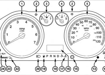
䡵 Instrument Cluster — Base . . . . . . . . . . . . . . . 200
䡵 Instrument Cluster — Premium . . . . . . . . . . . 201
䡵 Instrument Cluster Descriptions . . . . . . . . . . . 202
䡵 Electronic Vehicle Information Center (EVIC) —If Equipped . . . . . . . . . . . . . . . . . . . . . . . . . . 219
▫ EVIC Displays . . . . . . . . . . . . . . . . . . . . . . 221
▫ Distance To Empty (DTE) . . . . . . . . . . . . . . 226
▫ Average Fuel Economy / Fuel Saver Mode —If Equipped . . . . . . . . . . . . . . . . . . . . . . . . 227
▫ Trip Functions . . . . . . . . . . . . . . . . . . . . . . 228
▫ System (Customer Information Features) . . . . 229
▫ Compass / Temperature Display . . . . . . . . . 229
▫ Customer-Programmable Features(System Setup)
. . . . . . . . . . . . . . . . . . . . . . 232
194 UNDERSTANDING YOUR INSTRUMENT PANEL 䡵 Media Center 730N/430 (RER/REN/RBZ) — AM/FM Stereo Radio And CD/DVD/HDD/ NAV — If Equipped . . . . . . . . . . . . . . . . . . . . 238
▫ Operating Instructions — Voice CommandSystem — If Equipped . . . . . . . . . . . . . . . . . 238
▫ Operating Instructions — Uconnect™ phone
— If Equipped . . . . . . . . . . . . . . . . . . . . . . 239
▫ Clock Setting Procedure — RBZ Radio . . . . . 239
▫ Clock Setting Procedure — RER/RENRadio . . . . . . . . . . . . . . . . . . . . . . . . . . . . . 240
䡵 Media Center 130 (RES) — AM/FM Stereo
Radio With CD Player (MP3 AUX Jack). . . . . . . 243
▫ Operating Instructions — Radio Mode . . . . . 243
▫ Operation Instructions — CD Mode For CDAnd MP3 Audio Play . . . . . . . . . . . . . . . . . 246
▫ Notes On Playing MP3 Files . . . . . . . . . . . . 248
▫ Operation Instructions - Auxiliary Mode . . . . 251䡵 Media Center 130 (RES/RSC) — AM/FM
Stereo Radio With CD Player (MP3 AUX Jack) And Sirius Radio . . . . . . . . . . . . . . . . . . . . . . 252
▫ Operating Instructions — Radio Mode . . . . . 252
▫ Operation Instructions — CD Mode For CDAnd MP3 Audio Play . . . . . . . . . . . . . . . . . 258
▫ Notes On Playing MP3 Files . . . . . . . . . . . . 260
▫ List Button (CD Mode For MP3 Play) . . . . . . 263
▫ Info Button (CD Mode For MP3 Play) . . . . . . 263䡵 Universal Consumer Interface (UCI) —
If Equipped . . . . . . . . . . . . . . . . . . . . . . . . . . 264
▫ Connecting The iPod威 . . . . . . . . . . . . . . . . . 265▫ Using This Feature . . . . . . . . . . . . . . . . . . . 266
▫ Controlling The iPod威 Using RadioButtons . . . . . . . . . . . . . . . . . . . . . . . . . . . 266
▫ Play Mode . . . . . . . . . . . . . . . . . . . . . . . . . 266
▫ List Or Browse Mode . . . . . . . . . . . . . . . . . 268䡵 Uconnect™ Multimedia (Satellite Radio) — If Equipped (REN/RER/RBZ/RES Radios Only). . . . . . . . . . . . . . . . . . . . . . . . . . . . . . . 270
▫ System Activation . . . . . . . . . . . . . . . . . . . . 270
▫ Electronic Serial Number/SiriusIdentification Number (ESN/SID) . . . . . . . . . 270
▫ Selecting Uconnect™ Multimedia (Satellite)
Mode . . . . . . . . . . . . . . . . . . . . . . . . . . . . . 271
▫ Satellite Antenna . . . . . . . . . . . . . . . . . . . . . 271
▫ Reception Quality . . . . . . . . . . . . . . . . . . . . 271UNDERSTANDING YOUR INSTRUMENT PANEL 195
▫ Operating Instructions - Uconnect™
Multimedia (Satellite) Mode . . . . . . . . . . . . . 272
▫ Operating Instructions - Uconnect™ phone
(If Equipped)
. . . . . . . . . . . . . . . . . . . . . . . 274
䡵 Video Entertainment System (VES)™ —
If Equipped . . . . . . . . . . . . . . . . . . . . . . . . . . 274
䡵 Remote Sound System Controls —
If Equipped . . . . . . . . . . . . . . . . . . . . . . . . . . 276
▫ Radio Operation . . . . . . . . . . . . . . . . . . . . . 276
▫ CD Player . . . . . . . . . . . . . . . . . . . . . . . . . 277
䡵 CD/DVD Disc Maintenance . . . . . . . . . . . . . . 277
䡵 Radio Operation And Cellular Phones . . . . . . . 278
䡵 Climate Controls . . . . . . . . . . . . . . . . . . . . . . 278▫ Manual Heating And Air Conditioning
System . . . . . . . . . . . . . . . . . . . . . . . . . . . . 278
196 UNDERSTANDING YOUR INSTRUMENT PANEL ▫ Automatic Temperature Control (ATC) —
If Equipped . . . . . . . . . . . . . . . . . . . . . . . . 283
▫ Summer Operation . . . . . . . . . . . . . . . . . . . 288
▫ Winter Operation . . . . . . . . . . . . . . . . . . . . 288
▫ Vacation/Storage . . . . . . . . . . . . . . . . . . . . 289▫ Window Fogging And Frosting . . . . . . . . . . 289
▫ Outside Air Intake . . . . . . . . . . . . . . . . . . . 289
▫ Operating Tips . . . . . . . . . . . . . . . . . . . . . . 290INSTRUMENT PANEL FEATURES
UNDERSTANDING YOUR INSTRUMENT PANEL 197
1 — Headlight Switch 2 — Instrument Cluster 3 — Radio 4 — Upper Switch Bank 5 — Upper Glove Compartment 6 — Lower Glove Compartment
7 — 115v Power Inverter Outlet 8 — Power Outlet 9 — Lower Switch Bank 10 — Cup Holders 11 — Climate Controls 12 — Power Outlet/Cigar Lighter
13 — Transfer Case Position Switch 14 — Ignition Switch 15 — Hood Release 16 — Parking Brake Release
198 UNDERSTANDING YOUR INSTRUMENT PANEL SWITCH BANK BUTTON DESCRIPTION
Upper Switch Bank
The upper switch bank is located on the center of the instrument panel.
1. TOW/HAUL Refer to “Starting And Operating” for more information. 2. ESP OFF Refer to “Starting And Operating” for more information. 3. HAZARD WARNING FLASHER Refer to “What To Do In Emergencies” for more infor- mation. 4. 115V POWER INVERTER Refer to “Understanding The Features Of Your Vehicle” for more information. 5. REAR PARK ASSIST Refer to “Understanding The Features Of Your Vehicle” for more information. 6. TPMS LIGHT LOAD — IF EQUIPPED Refer to “Starting And Operating” for more information.
Lower Switch Bank
The lower switch bank is located on the center of the instrument panel.
UNDERSTANDING YOUR INSTRUMENT PANEL 199
1. HEATED SEATS Refer to “Understanding The Features Of Your Vehicle” for more information. 2. VENTILATED SEATS Refer to “Understanding The Features Of Your Vehicle” for more information. 3. HEATED STEERING WHEEL Refer to “Understanding The Features Of Your Vehicle” for more information.
200 UNDERSTANDING YOUR INSTRUMENT PANEL INSTRUMENT CLUSTER — BASE
INSTRUMENT CLUSTER — PREMIUM
UNDERSTANDING YOUR INSTRUMENT PANEL 201
202 UNDERSTANDING YOUR INSTRUMENT PANEL INSTRUMENT CLUSTER DESCRIPTIONS
1. Tachometer The Tachometer indicates engine speed in revolutions per minute.
CAUTION!
Do not operate the engine with the tachometer pointer at high RPM for extended periods. Engine damage may occur.
2. Turn Signal Indicators
The arrow will flash with the exterior turn signal when the turn signal lever is operated.
NOTE: • A continuous chime will sound if the vehicle is driven more than 1 mile (1.6 km) with either turn signal on.
• Check for an inoperative outside light bulb if either indicator remains on and does not flash, or flashes at a rapid rate. 3. Fuel Gauge Shows level of fuel in tank when ignition switch is in the ON position. 4. Temperature Gauge The temperature gauge shows engine coolant tempera- ture. Any reading within the normal range indicates that the engine cooling system is operating satisfactorily. The gauge pointer will likely indicate a higher tempera- ture when driving in hot weather, up mountain grades, or when towing a trailer. It should not be allowed to exceed the upper limits of the normal operating range.
CAUTION!
Driving with a hot engine cooling system could damage your vehicle. If temperature gauge reads “H” pull over and stop the vehicle. Idle the vehicle with the air conditioner turned off until the pointer drops back into the normal range. If the pointer remains on the “H” and you hear continuous chimes, turn the engine off imme- diately, and call an authorized dealership for service.
WARNING!
A hot engine cooling system is dangerous. You or others could be badly burned by steam or boiling coolant. You may want to call an authorized dealership for service if your vehicle overheats. If you decide to look under the hood yourself, see “Maintaining Your Vehicle”. Follow the warnings under the Cooling Sys- tem Pressure Cap paragraph.
UNDERSTANDING YOUR INSTRUMENT PANEL 203
5. Speedometer The speedometer shows the vehicle speed in miles per hour and/or kilometers per hour (mph/km/h). 6. 4 LOW
This light alerts the driver that the vehicle is in the four-wheel drive LOW mode. The front and rear driveshafts are mechanically locked to- gether forcing the front and rear wheels to rotate at the same speed. Low range provides a greater gear reduction ratio to provide increased torque at the wheels.