- Download PDF Manual
-
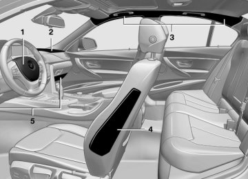
Height Adjust the head restraint so that its center is ap‐ proximately at ear level. Distance Adjust the distance so that the head restraint is as close as possible to the back of the head. If necessary, adjust the distance by adjusting the tilt of the backrest.
Putting on the belt Lay the belt, without twisting, snugly
across the lap and shoulders, as close to the body as possible. Make sure that the belt lies low around the hips in the lap area and does not press on the abdomen. Otherwise, the belt can slip over the hips in the lap area in a frontal im‐ pact and injure the abdomen. The safety belt must not lie across the neck, rub on sharp edges, be routed over solid or breaka‐ ble objects, or be pinched.◀
Reduction of restraining effect Avoid wearing clothing that prevents the belt from fitting properly, and pull the shoulder belt periodically to readjust the tension across your lap; otherwise, the retention effect of the safety belt may be reduced.◀
Buckling the belt
Make sure you hear the latch plate engage in the belt buckle.
Unbuckling the belt 1. Hold the belt firmly. 2. Press the red button in the belt buckle. 3. Guide the belt back into its reel. Safety belt reminder for driver's seat and front passenger seat
The indicator lamp flashes or lights up and a signal sounds. Make sure that the safety belts are positioned correctly. The safety belt reminder is active at speeds
Online Edition for Part no. 01 40 2 903 880 - 07 12 490
49
Controls
Adjusting
Adjusting the height
▷ To raise: pull. ▷ To lower: press the button, arrow 1, and
push the head restraint down.
Tilt Three different tilt positions are available.
▷ Forward: pull the top edge of the head re‐
straint forward, arrow 1.
▷ Back: press the button, arrow 2. The head
restraint folds as far back as possible.
Removing Only remove the head restraint if no one will be sitting in the seat in question.
1. Pull the head restraint upward as far as pos‐
sible.
2. Press the button, arrow 1, and pull the head
restraint out completely.
Before transporting passengers Reinstall the head restraint before trans‐ porting anyone in the seat; otherwise, the pro‐ tective function of the head restraint is unavail‐ able.◀
Rear head restraints Correctly adjusted head restraint A correctly adjusted head restraint reduces the risk of injury to cervical vertebrae in the event of an accident.
Adjusting the head restraint Correctly adjust the head restraints of all occupied seats; otherwise, there is an increased risk of injury in an accident.◀
Height Adjust the head restraint so that its center is ap‐ proximately at ear level.
50
Online Edition for Part no. 01 40 2 903 880 - 07 12 490
Adjusting the height
Adjusting
Controls
▷ To raise: pull. ▷ To lower: press the button, arrow 1, and
push the head restraint down.
The center head restraint cannot be adjusted in elevation.
Folding down head restraints
Extending/retracting head restraint Only fold down head restraint if no pas‐
sengers are in the rear. Fold out retracted headr‐ ests again if passengers are being carried in the rear; otherwise, there is increased risk of injury in the event of an accident.◀
1. Pull the head restraint upward as far as pos‐
sible.
2. Press the button, arrow 1, and pull the head
restraint out completely.
Before transporting passengers Reinstall the head restraint before trans‐ porting anyone in the seat; otherwise, the pro‐ tective function of the head restraint is unavail‐ able.◀
Seat and mirror memory General information
▷ To lower flaps: press the button, arrow 1,
and press down the head restraint.
▷ Fold back up: pull up head restraints.
Removing Only remove the head restraint if no one will be sitting in the seat in question.
Two different driver's seat and exterior mirror positions can be stored and retrieved for each remote control. Settings for the backrest width and lumbar support are not stored in memory. Storing 1. Switch on the ignition. 2. Set the desired position.
Online Edition for Part no. 01 40 2 903 880 - 07 12 490
51
Controls
Adjusting
3.
Press the button. The LED in the
button lights up.
4. Press the desired button 1 or 2. The LED
goes out.
If the M button is pressed accidentally:
Press the button again. The LED goes out.
Calling up settings
Do not retrieve the memory while driving Do not retrieve the memory setting while driving, as an unexpected movement of the seat or steering wheel could result in an accident.◀
Comfort function 1. Open the driver's door. 2. Switch off the ignition. 3. Briefly press the desired button 1 or 2. The corresponding seat position is performed automatically. The procedure stops when a switch for adjust‐ ing the seat or one of the buttons is pressed. Safety mode 1. Close the driver's door or switch on the ig‐
nition.
2. Press and hold the desired button 1 or 2 until
the adjustment procedure is completed.
Calling up of a seat position deactivated After a brief period, the calling up of stored seat positions is deactivated to save battery power. To reactivate calling up of a seat position: ▷ Open and close the door or trunk lid. ▷ Press a button on the remote control. ▷ Press the Start/Stop button.
Mirrors Exterior mirrors At a glance
1 Adjusting 2 Left/right, Automatic Curb Monitor 3 Fold in and out
General information The mirror on the passenger side is more curved than the driver's side mirror.
Estimating distances correctly Objects reflected in the mirror are closer than they appear. Do not estimate the distance to the traffic behind you based on what you see in the mirror, as this will increase your risk of an accident.◀ Depending on how the vehicle is equipped, the mirror setting is stored for the remote control in use. When the vehicle is unlocked via the remote control, the position is automatically retrieved if the setting for this function is active. Selecting a mirror
To change over to the other mirror: Slide the mirror changeover switch.
Adjusting electrically
The setting corresponds to the direction in which the button is pressed.
52
Online Edition for Part no. 01 40 2 903 880 - 07 12 490
Saving positions Seat and mirror memory, refer to page 51
Adjusting manually If an electrical malfunction occurs, for example, press the edges of the mirror glass. Automatic Curb Monitor When the reverse gear is engaged, the mirror glass tilts downward slightly on the front pas‐ senger side. This improves your view of the curb and other low-lying obstacles when parking, for example.Activating
1.
Slide the mirror changeover switch
to the driver's side mirror position.
2. Engage transmission position R.
Deactivating Slide the mirror changeover switch to the pas‐ senger's side mirror position. Fold in and out
Press the button.
Possible up to approx. 15 mph/20 km/h. For example, this is advantageous ▷ In car washes. ▷ In narrow streets. ▷ For folding back mirrors that were folded
away manually.
Mirrors that were folded in are folded out auto‐ matically at a speed of approx. 25 mph/40 km/h.
Fold in the mirror in a car wash Before entering an automatic car wash, fold in the exterior mirrors by hand or with the button; otherwise, they could be damaged, de‐ pending on the width of the vehicle.◀
Adjusting
Controls
Automatic heating Both exterior mirrors are automatically heated whenever the engine is running. Automatic dimming feature Both exterior mirrors are automatically dimmed. Photocells are used for control in the Interior rear view mirror, refer to page 53. Interior rearview mirror Reducing the blinding effect
From behind when driving at night: turn the knob.
Interior rearview mirror, automatic dimming feature The concept
Photocells are used for control: ▷ In the mirror glass. ▷ On the back of the mirror.
Online Edition for Part no. 01 40 2 903 880 - 07 12 490
53
Controls
Adjusting
Functional requirement For proper operation: ▷ Keep the photocells clean. ▷ Do not cover the area between the inside
rearview mirror and the windshield.
Switching on/off
Press the button.
▷ On: the LED lights up. ▷ Off: the LED goes out.
Steering wheel General information
Do not adjust while driving Do not adjust the steering wheel while driving; otherwise, an unexpected movement could result in an accident.◀
Adjusting
1. Fold the lever down. 2. Move the steering wheel to the preferred height and angle to suit your seating posi‐ tion.
3. Fold the lever back. Steering wheel heating
54
Online Edition for Part no. 01 40 2 903 880 - 07 12 490
Transporting children safely
Controls
Transporting children safely Vehicle equipment All standard, country-specific and optional equipment that is offered in the model series is described in this chapter. Therefore, equipment is also described that is not available in a vehicle, e. g., because of the selected optional equip‐ ment or country variant. This also applies for safety-related functions and systems.
tomatic deactivation of front passenger airbags, refer to page 94.
Deactivating the front passenger airbags If a child restraint fixing system is used in the front passenger seat, the front passenger airbags must be deactivated; otherwise, there is an increased risk of injury to the child when the airbags are triggered, even with a child restraint fixing system.◀
The right place for children Note
Children in the vehicle Do not leave children unattended in the vehicle; otherwise, they could endanger them‐ selves and other persons, e.g., by opening the doors.◀
Children should always be in the rear Accident research shows that the safest place for children is in the back seat.
Transporting children in the rear Only transport children younger than
13 years of age or shorter than 5 ft/150 cm in the rear in child restraint fixing systems provided in accordance with the age, weight and size of the child; otherwise, there is an increased risk of in‐ jury in an accident. Children 13 years of age or older must wear a safety belt as soon as a suitable child restraint fixing system can no longer be used, due to their age, weight and size.◀
Children on the front passenger seat Should it ever be necessary to use a child re‐ straint fixing system in the front passenger seat, make sure that the front, knee and side airbags on the front passenger side are deactivated. Au‐
Installing child restraint fixing systems Before mounting Before mounting child restraint fixing systems, ensure that the rear seat backrests are locked. Notes
Manufacturer's information for child re‐ straint fixing systems
To select, mount and use child restraint fixing systems, observe the information provided by the system manufacturer; otherwise, the pro‐ tective effect can be impaired.◀
On the front passenger seat Deactivating airbags After installing a child restraint fixing system in the front passenger seat, make sure that the front, knee and side airbags on the front pas‐ senger side are deactivated. Deactivate the front passenger airbags auto‐ matically, refer to page 94
Deactivating the front passenger airbags If a child restraint fixing system is used in the front passenger seat, the front passenger airbags must be deactivated; otherwise, there is
Online Edition for Part no. 01 40 2 903 880 - 07 12 490
55
Controls
Transporting children safely
an increased risk of injury to the child when the airbags are triggered, even with a child restraint fixing system.◀
Seat position and height Before installing a child restraint fixing system, move the front passenger seat as far back as possible and adjust its height to the highest po‐ sition to obtain the best possible position for the belt and to offer optimal protection in the event of an accident. Do not change the seat position and height after this. Backrest width Adjustable backrest width: before installing a child restraint fixing system in the front passen‐ ger seat, open the backrest width completely. Do not change the backrest width again and do not call up a memory position.
Backrest width for the child seat Before installing a child restraint fixing
system in the front passenger seat, the backrest width must be opened completely. Do not change the adjustment after this; otherwise, the stability of the child seat will be reduced.◀
Child seat security
The rear safety belts and the front passenger safety belt can be locked against pulling out for mounting the child restraint fixing systems.
Locking the safety belt 1. Pull out the belt webbing completely. 2. Secure the child restraint fixing system with
the belt.
3. Allow the belt webbing to be pulled in and pull it taut against the child restraint fixing system. The safety belt is locked.
Unlocking the safety belt 1. Unbuckle the belt buckle. 2. Remove the child restraint fixing system. 3. Allow the belt webbing to be pulled in com‐
pletely.
LATCH child restraint fixing system LATCH: Lower Anchors and Tether for Children. Note
Manufacturer's information for LATCH child restraint fixing systems
To mount and use the LATCH child restraint fix‐ ing systems, observe the operating and safety information from the system manufacturer; oth‐ erwise, the level of protection may be reduced.◀
Mounts for the lower LATCH anchors Correctly engage the lower LATCH an‐ chors
Make sure that the lower LATCH anchors have properly engaged and that the child restraint fix‐ ing system is resting snugly against the back‐ rest; otherwise, the degree of protection offered may be reduced.◀ Before mounting the LATCH child restraint fix‐ ing system, pull the belt away from the child re‐ straint fixing system.
56
Online Edition for Part no. 01 40 2 903 880 - 07 12 490
Transporting children safely
Controls
Without a through-loading system: Position
Mounts for the lower LATCH anchors are lo‐ cated in the gap between the seat and backrest.
With a through-loading system: Position
Child restraint fixing system with a tether strap Note
LATCH mounting eyes Only use the mounting eyes for the upper LATCH retaining strap to secure child restraint fixing systems; otherwise, the mounting eyes could be damaged.◀
Mounting points
Depending on the vehicle equipment, there are two outer or three mounting points for child re‐ straint fixing systems with a tether strap.
Retaining strap guide
Retaining strap Make sure that the upper retaining strap is
not routed over the head restraints or sharp edges and is free of twisting on its way to the upper mounting point; otherwise, the belt can‐ not properly secure the child restraint fixing sys‐ tem in an accident.◀
Mounts for the lower LATCH anchors are lo‐ cated behind the indicated covers.
Mounting LATCH child restraint fixing systems 1. Mount the child restraint fixing system; refer to the operating instructions of the system. 2. Ensure that both LATCH anchors are prop‐
erly connected.
Online Edition for Part no. 01 40 2 903 880 - 07 12 490
57
Controls
Transporting children safely
Locking the doors and windows Rear doors
1 Direction of travel 2 Head restraint. 3 Hook for upper retaining strap 4 Mounting point/eye 5 Rear window shelf 6 Seat backrest 7 Upper retaining strap
Attaching the upper retaining strap to the mounting point 1. Remove the mounting point cover. 2. Raise or remove head restraints. 3. Guide the upper retaining strap between the
supports of the head restraint.
4. Attach the hook of the retaining strap to the
mounting eye.
5. Tighten the retaining strap by pulling it
down.
6. Lower and lock head restraints as needed.
Push the locking lever on the rear doors down. The door can now be opened from the outside only.
Safety switch for the rear
Press the button on the driver's door if children are being transported in the
rear. This locks various functions so that they cannot be operated from the rear: safety switch, refer to page 42.
58
Online Edition for Part no. 01 40 2 903 880 - 07 12 490
Driving Vehicle equipment All standard, country-specific and optional equipment that is offered in the model series is described in this chapter. Therefore, equipment is also described that is not available in a vehicle, e. g., because of the selected optional equip‐ ment or country variant. This also applies for safety-related functions and systems.
Start/Stop button The concept
Pressing the Start/Stop button switches the ignition on or off and starts the engine. Automatic transmission: The en‐ gine starts if the brake is de‐
pressed while pressing the Start/Stop button. Manual transmission: the engine starts if the clutch pedal is depressed when the Start/Stop button is pressed.
Ignition on Automatic transmission: Press the Start/Stop button but do not depress the brake. Manual-shift transmission: press the Start/Stop button, and do not press on the clutch pedal at the same time. All vehicle systems are ready for operation. Most of the indicator and warning lamps in the instrument cluster light up for varying lengths of time. To save battery power when the engine is off, switch off the ignition and any unnecessary electronic systems/power consumers. The ignition switches off automatically: ▷ When the vehicle is locked, if the low beams
are switched on.
Driving
Controls
▷ Shortly before the battery is discharged
completely, so that the engine can still be started.
▷ If the engine is switched off and the ignition
is switched on, the system automatically switches to the radio ready state when the door is opened if the lights are switched off or the daytime running lights are switched on. If the engine is switched off and the ignition is switched on, the system automatically switches to the radio ready state when the door is opened if the lights are switched off.
Ignition off Automatic transmission: Press the Start/Stop button again, but do not depress the brake. Manual-shift transmission: press the Start/Stop button again, and do not press on the clutch pedal at the same time. All indicator lamps in the instrument cluster go out. To save battery power when the engine is off, switch off the ignition and any unnecessary electronic systems/power consumers.
Transmission position P with the ignition off
When the ignition is switched off, position P is engaged automatically. When in an automatic car wash, for example, ensure that the ignition is not switched off accidentally.◀ Ignition automatically cuts off while the vehicle is stationary and the engine is stopped: ▷ During locking, also with the low beams ac‐
tivated.
▷ Shortly before the battery is discharged
completely, so that the engine can still be started. This function is only available when the low beams are switched off.
Online Edition for Part no. 01 40 2 903 880 - 07 12 490
59
Controls
Driving
▷ When opening and closing the driver door, if the driver's seat belt is unbuckled and the low beams are switched off.
▷ While the driver's seat belt is unbuckled, if the driver's door is open and the low beams are switched off.
When the ignition is switched off, by opening or closing the driver's door or unbuckling the driv‐ er's seat belt, the radio ready state remains ac‐ tive. Radio ready state Activate radio ready state: ▷ When the ignition is switched off: press ON/
OFF button on the radio.
▷ When the engine is running: press the Start/
Stop button.
Some electronic systems/power consumers re‐ main ready for operation. Radio ready state switches off automatically: ▷ After approx. 8 minutes. ▷ When the vehicle is locked using the central
locking system.
▷ Shortly before the battery is discharged
completely, so that the engine can still be started.
Starting the engine General information
Enclosed areas Do not let the engine run in enclosed
areas; otherwise, breathing of exhaust fumes may lead to loss of consciousness and death. The exhaust gases contain carbon monoxide, an odorless and colorless but highly toxic gas.◀
Unattended vehicle Do not leave the vehicle unattended with the engine running; doing so poses a risk of dan‐ ger.
Before leaving the vehicle with the engine run‐ ning, set the parking brake and place the trans‐ mission in position P or neutral to prevent the vehicle from moving.◀
Repeated starting in quick succession Avoid repeated unsuccessful attempts to start the vehicle or starting the vehicle several times in quick succession. Otherwise, the fuel is not burned or is inadequately burned, posing a risk of overheating and damage to the catalytic converter.◀ Do not wait for the engine to warm up while the vehicle remains stationary. Start driving at mod‐ erate engine speeds. Manual transmission Starting the engine 1. Depress the brake pedal. 2. Press on the clutch and shift to neutral. 3. Press the Start/Stop button. The ignition is activated automatically for a cer‐ tain time and is stopped as soon as the engine starts. Automatic transmission Starting the engine 1. Depress the brake pedal. 2. Press the Start/Stop button. The ignition is activated automatically for a cer‐ tain time and is stopped as soon as the engine starts.
Engine stop General information
Take the remote control with you Take the remote control with you when
leaving the vehicle so that children, for example, cannot start the engine.◀
60
Online Edition for Part no. 01 40 2 903 880 - 07 12 490
Set the parking brake and further secure the vehicle as required
Set the parking brake firmly when parking; oth‐ erwise, the vehicle could roll. On steep upward and downward inclines, further secure the vehi‐ cle, for example, by turning the steering wheel in the direction of the curb. ◀
Before driving into a car wash In order for the vehicle to be able to roll into a car wash, heed the information regarding Washing in automatic car washes, refer to page 213. Manual transmission Switching off the engine 1. With the vehicle at a standstill, press the
Start/Stop button.
2. Shift into first gear or reverse. 3. Set the parking brake. Automatic transmission Switching off the engine 1. Engage transmission position P with the ve‐
hicle stopped.
2. Press the Start/Stop button. The engine is switched off. The radio ready state is switched on.
3. Set the parking brake.
Auto Start/Stop function The concept The Auto Start/Stop function helps save fuel. The system switches off the engine during a stop, e.g., in a traffic congestion or at traffic lights. The ignition remains switched on. The engine starts again automatically for driving off. Certain vehicle components may experience additional wear as a result of this system.
Driving
Controls
Automatic mode The Auto Start/Stop function is operational after each engine start. This function is activated at speeds faster than about 3 mph, approx. 5 km/h. Engine stop The engine is switched off automatically during a stop under the following conditions: Manual transmission: ▷ Neutral is engaged and the clutch pedal is
not pressed.
▷ The driver's safety belt is buckled or the
driver's door is closed.
Automatic transmission: ▷ The selector lever is in transmission position
D.
▷ Brake pedal remains depressed while the
vehicle is stopped.
▷ The driver's safety belt is buckled or the
driver's door is closed.
The air flow of the air conditioner is reduced when the engine is switched off. Displays in the instrument cluster
The READY display in the tach‐ ometer signals that the Auto Start/Stop function is ready to start the engine automatically.
The display indicates that the conditions for an automatic en‐ gine stop have not been satisfied.
Note The engine is not switched off automatically in the following situations: ▷ External temperature below approx.
+37 ℉/+3 ℃.
Online Edition for Part no. 01 40 2 903 880 - 07 12 490
61
Controls
Driving
▷ The external temperature is high and auto‐
matic climate control is running.
▷ The passenger compartment has not yet
been heated or cooled to the required level. ▷ The engine is not yet at operating tempera‐
ture.
▷ The wheels are at a sharp angle or the steer‐
ing wheel is being turned.
▷ After driving in reverse. ▷ Fogging of the windows when the automatic
climate control is switched on.
▷ The vehicle battery charge is very low. ▷ The engine compartment lid is unlocked. ▷ The parking assistant is activated. ▷ Stop-and-go traffic. ▷ The transmission selector lever is in position
N or S/M.
Starting the engine The engine starts automatically under the fol‐ lowing conditions: ▷ Manual transmission:
The clutch pedal is pressed.
▷ Automatic transmission:
By releasing the brake pedal.
After the engine starts, accelerate as usual. Safety mode After the engine switches off automatically, it will not start again automatically if any one of the following conditions are met. ▷ The driver's safety belt is unbuckled and the
driver's door is open.
▷ The hood was unlocked. Some indicator lamps light up for varying lengths of time. The engine can only be started via the Start/ Stop button.
Note Even if driving away was not intended, the de‐ activated engine starts up automatically in the following situations: ▷ Excessive warming of the passenger com‐
partment when the cooling function is switched on.
▷ The steering wheel is turned. ▷ Automatic transmission: the transmission position is changed from D to N, R, or M/S. ▷ Automatic transmission: the transmission position is changed from P to N, D, R, or M/ S.
▷ The vehicle begins rolling. ▷ Fogging of the windows when the automatic
climate control is switched on.
▷ The vehicle battery charge is very low. ▷ Excessive cooling of the passenger com‐ partment when the heating is switched on. ▷ Low brake vacuum pressure; this can occur, for example, if the brake pedal is depressed a number of times in succession.
Activating/deactivating the system manually Using the button
Press the button.
▷ LED comes on: Auto Start Stop function is
deactivated. The engine is started during an automatic engine stop.
62
Online Edition for Part no. 01 40 2 903 880 - 07 12 490
The engine can only be stopped or started via the Start/Stop button.
Releasing
Driving
Controls
▷ LED goes out: Auto Start Stop function is
activated.
Switching off the vehicle during an automatic engine stop During an automatic engine stop, the vehicle can be switched off permanently, e.g., when leaving it. 1. Press the Start/Stop button. The ignition is switched off. The Auto Start/Stop function is deactivated. Automatic transmission: the transmission position P is engaged automatically.
2. Set the parking brake. Engine start as usual via Start/Stop button. Automatic deactivation In certain situations, the Auto Start/Stop func‐ tion is deactivated automatically for safety rea‐ sons, such as when the driver is detected to be absent. Malfunction The Auto Start/Stop function no longer switches of the engine automatically. A Check Control message is displayed. It is possible to continue driving. Have the system checked.
Parking brake Applying The lever automatically engages after being pulled up.
The indicator lamp lights up red. The parking brake is set. Lower lamp: indicator lamp in Canadian models
Raise lever slightly, press the button and guide the lever down. Notes
Use while driving If on a rare occasion it is necessary to use the parking brake while driving, do not use ex‐ cessive force when applying it. When using it, keep the button on the lever depressed. Otherwise, using excessive force when applying the parking brake may cause the rear wheels to lock, resulting in fishtailing.◀ To prevent corrosion and braking control on one side only, lightly apply the parking brake period‐ ically while coasting, if traffic conditions permit. The brake lamps will not light up if the parking brake is engaged.
Turn signal, high beams, headlamp flasher Turn signal
Do not fold in the exterior mirrors During driving and during the operation of the turn signals/warning flashers, do not fold in the exterior mirror, or else the additional flasher lights in the exterior mirror do not have the pre‐ scribed position and can only be poorly de‐ tected.◀
Online Edition for Part no. 01 40 2 903 880 - 07 12 490
63
Controls
Driving
Using turn signals
High beams, headlamp flasher
Press the lever beyond the resistance point. To switch off manually, press the lever to the re‐ sistance point. Unusually rapid flashing of the indicator lamp in‐ dicates that a turn signal bulb has failed. Triple turn signal activation Press the lever to the resistance point. The turn signal flashes three times. The function can be activated or deactivated: 1. "Settings" 2. "Lighting" 3. "Triple turn signal"
▷ High beams, arrow 1. ▷ Headlamp flasher, arrow 2.
Washer/wiper system Switching the wipers on/off and brief wipe
Do not switch on the wipers if frozen Do not switch on the wipers if they are fro‐
zen onto the windshield; otherwise, the wiper blades and the windshield wiper motor may be damaged.◀
No wiper operation on dry windshield Do not use the windshield wipers if the
windshield is dry, as this may damage the wiper blades or cause them to become worn more quickly.◀
Switching on
Signaling briefly Press the lever to the resistance point and hold it there for as long as you want the turn signal to flash.
Press the wiper levers up. The lever automatically returns to its initial po‐ sition when released.
64
Online Edition for Part no. 01 40 2 903 880 - 07 12 490
▷ Normal wiping speed: press up once.
The wipers switch to intermittent operation when the vehicle is stationary.
▷ Fast wiping speed: press up twice or press
once beyond the resistance point. The wipers switch to normal speed when the vehicle is stationary.
Switching off and brief wipe
Press the wiper levers down. The lever automatically returns to its initial po‐ sition when released. ▷ Brief wipe: press down once. ▷ To switch off normal wipe: press down once. ▷ To switch off fast wipe: press down twice. Intermittent operation or rain sensor The concept The rain sensor automatically controls the time between wipes depending on the intensity of the rainfall. The sensor is located on the wind‐ shield, directly behind the interior rearview mir‐ ror.
Driving
Controls
Activating/deactivating
Press the button on the wiper lever. The LED in the steering column stalk lights up.
Deactivate the rain sensor in car washes Deactivate the rain sensor when passing through an automatic car wash; otherwise, dam‐ age could be caused by undesired wiper activa‐ tion.◀
Setting the frequency or sensitivity of the rain sensor
Turn the thumbwheel.
Clean the windshield, headlamps
Pull the lever.
Online Edition for Part no. 01 40 2 903 880 - 07 12 490
65
Controls
Driving
The system sprays washer fluid on the wind‐ shield and activates the wipers briefly. In addition, the headlamps are cleaned at regular intervals when the vehicle lights are switched on.
Do not use the washer system at freezing temperatures
Do not use the washers if there is any danger that the fluid will freeze on the windshield; oth‐ erwise, your vision could be obscured. For this reason, use antifreeze. Avoid using the washer when the reservoir is empty; otherwise, you could damage the pump.◀
Windshield washer nozzles The windshield washer nozzles are automati‐ cally heated while the ignition is switched on. Fold-out position of the wipers Required when changing the wiper blades or under frosty conditions, for example. 1. Switch off the ignition. 2. Under frosty conditions, ensure that the
wiper blades are not frozen onto the wind‐ shield.
3. Press the wiper lever up beyond the point of resistance and hold it for approx. 3 seconds, until the wiper remains in a nearly vertical position.
After the wipers are folded back down, the wiper system must be reactivated.
Fold the wipers back down Before switching the ignition on, fold the wipers back down to the windshield; otherwise, the wipers may become damaged when they are switched on.◀ 1. Switch on the ignition. 2. Press the wiper levers down. The wipers
move to their resting position and are ready for operation.
Washer fluid General information
Antifreeze for washer fluid Antifreeze is flammable. Therefore, keep
it away from sources of ignition. Only keep it in the closed original container and inaccessible to children. Follow the instructions on the container.◀
Washer fluid reservoir Adding washer fluid Only add washer fluid when the engine is
cool, and then close the cover completely to avoid contact between the washer fluid and hot engine parts. Otherwise, there is the danger of fire and a risk to personal safety if the fluid is spilled.◀
All washer nozzles are supplied from one reser‐ voir. Fill with water and – if required – with a washer antifreeze, according to the manufacturer's rec‐ ommendations. Mix the washer fluid before adding to maintain the correct mixing ratio. For the capacity, refer to technical data.
66
Online Edition for Part no. 01 40 2 903 880 - 07 12 490
Manual transmission Shifting
Shifting into 5th or 6th gear When shifting into 5th or 6th gear, push the gearshift lever to the right; otherwise inad‐ vertent shifting into the 3rd or 4th gear could lead to engine damage.◀
Reverse gear Select only when the vehicle is stationary. When the gearshift lever is pressed to the left, a slight resistance needs to be overcome.
Automatic transmission with Steptronic Transmission positions D Drive, automatic position Position for normal vehicle operation. All for‐ ward gears are available. R is Reverse Select only when the vehicle is stationary. N is Neutral Use in automatic car washes, for example. The vehicle can roll. When the ignition is switched off, refer to page 59, position P is engaged automatically. P Park Select only when the vehicle is stationary. The drive wheels are blocked. P is engaged automatically: ▷ After the engine is switched off when the
vehicle is in radio ready state, refer to page 60, or when the ignition is switched off, refer to page 59, and when position R or D is engaged.
Driving
Controls
▷ With the ignition is off, if position N is en‐
gaged.
▷ If the safety belt is unbuckled, the driver's door is opened, and the brake pedal is not pressed while the vehicle is stationary and transmission position R or D is engaged.
Before exiting the vehicle, make sure that posi‐ tion P of the automatic transmission is engaged. Otherwise, the vehicle may begin to roll. Kickdown Kickdown is used to achieve maximum driving performance. Press on the gas pedal beyond the resistance point at the full throttle position. Engaging the transmission position ▷ Transmission position P can only be disen‐ gaged if the engine is running and the brake pedal is pressed.
▷ With the vehicle stationary, press on the brake pedal before shifting out of P or N; otherwise, the shift command will not be executed: shift lock.
Depress the brake until you start driv‐ ing
To prevent the vehicle from creeping after you select a driving position, maintain pres‐ sure on the brake pedal until you are ready to start.◀
Engaging D, R and N
Briefly push the selector lever in the desired di‐ rection, beyond a resistance point if necessary.
Online Edition for Part no. 01 40 2 903 880 - 07 12 490
67
Controls
Driving
After releasing the selector lever, it returns to its center position.
Press unlock button, in order to: ▷ Engage R. ▷ Shift out of P.
Engaging P
Press button P.
Sport program DS and manual mode M/ Activating the sport program
Push the selector lever to the left out of trans‐ mission position D.
DS is displayed in the instrument cluster. The sport program of the transmission is acti‐ vated.
Activating the M/S manual mode 1. Push the selector lever to the left out of
transmission position D.
2. Push the selector lever forward or backward. Manual mode becomes active and the gear is changed. The engaged gear is displayed in the instrument cluster, e.g., M1. Once maximum engine speed is attained, M/S manual mode is automatically upshifted as needed. Switching to manual mode ▷ To shift down: press the selector lever for‐
ward.
▷ To shift up: pull the selector lever rearwards. Gears will only be shifted at appropriate engine and road speeds, e.g., downshifting is not pos‐ sible if the engine speed is too high. The selected gear is briefly displayed in the in‐ strument cluster, followed by the current gear. Sport automatic transmission: prevent automatic upshifting in M/S manual mode For vehicles with Sport automatic transmis‐ sions, automatic shift operations are not per‐ formed, at maximum engine speed for example, if one of the following conditions is met: ▷ DSC deactivated. ▷ TRACTION activated. ▷ SPORT+ activated. In addition, the kickdown is deactivated. Ending the sport program/manual mode Push the selector lever to the right.
68
Online Edition for Part no. 01 40 2 903 880 - 07 12 490
Driving
Controls
D is displayed in the instrument cluster. Shift paddles for Sport automatic transmission
The shift paddles on the steering wheel allow you to shift gears quickly while keeping both hands on the steering wheel. If the shift paddles on the steering wheel are used to shift gears in automatic mode, the trans‐ mission temporarily switches to manual mode. If the shift paddles are not used and the vehicle is not accelerated for a certain time, the system switches back into automatic mode if the selec‐ tor lever is in transmission position D. ▷ Shift up: pull right shift paddle. ▷ Shift down: pull left shift paddle. The vehicle only shifts up or down at appropriate engine and road speeds, e.g., it does not shift down if the engine speed is too high. The selected gear is briefly displayed in the in‐ strument cluster, followed by the current gear.
Displays in the instrument cluster
The transmission position is dis‐ played, e.g.: P.
Online Edition for Part no. 01 40 2 903 880 - 07 12 490
69
Controls
Displays
Displays Vehicle equipment All standard, country-specific and optional equipment that is offered in the model series is described in this chapter. Therefore, equipment
Instrument cluster Overview, instrument cluster
is also described that is not available in a vehicle, e. g., because of the selected optional equip‐ ment or country variant. This also applies for safety-related functions and systems.
1 Fuel gauge 76
2 Speedometer 3 Indicator/warning lamps 74
4 Tachometer 765 Engine oil temperature 76
6 Current fuel consumption 77
7 Electronic displays 72
8 Display/reset miles 7670
Online Edition for Part no. 01 40 2 903 880 - 07 12 490
Overview, instrument cluster with enhanced features
Displays
Controls
1 Fuel gauge 76
2 Speedometer 3 Indicator/warning lamps 74
4 Tachometer 765 Engine oil temperature 76
6 Current fuel consumption 77
7 Electronic displays 72
8 Display/reset miles 76Online Edition for Part no. 01 40 2 903 880 - 07 12 490
71
Controls
Displays
Electronic displays Overview, instrument cluster
1 Messages, e.g. Check Control 73
Time 76
Date 76
External temperature 76
Selection lists 81
Service requirements 77Miles/trip miles 76
Computer 812 Transmission display 69
Gear shift indicator 79
3 Status, Driving Experience Switch 113
72
Online Edition for Part no. 01 40 2 903 880 - 07 12 490
Overview, instrument cluster with enhanced features
Displays
Controls
Navigation display, see user's manual for Navigation, Entertainment and Communi‐ cation.
2 Energy recovery 77
Transmission display 69
Current fuel consumption 77
ECO PRO 1673 Messages, e.g. Check Control 73
Service requirements 77
In addition, an acoustic signal may be output and a text message may appear on the Control Dis‐ play.
1 Time 76
External temperature 76
Date 76
Selection list, such as for the radio 81
Speed limit detection 79
Computer 81
Miles/trip miles 76Check Control The concept The Check Control system monitors functions in the vehicle and notifies you of malfunctions in the monitored systems. A Check Control message is displayed as a combination of indicator or warning lamps and text messages in the instrument cluster and in the Head-up Display.
Online Edition for Part no. 01 40 2 903 880 - 07 12 490
73
Controls
Displays
Indicator/warning lamps
The indicator and warning lamps can light up in a variety of combinations and colors. Several of the lamps are checked for proper functioning and light up temporarily when the engine is started or the ignition is switched on.
Overview: indicator/warning lamps
Symbol Function or system
Turn signal
Front fog lamps
Rear fog lamp
High beams
High-beam Assistant
Parking lamps, headlamp control
Active Cruise Control
Vehicle detection, Active Cruise Control
Symbol Function or system
Collision warning
Adjustable speed limit
Cruise control
Lane departure warning
DSC Dynamic Stability Control
DSC Dynamic Stability Control is de‐ activated or DTC Dynamic Traction Control is activated Tire Pressure Monitor Flat Tire Monitor Safety belts
Airbag system
Steering system
Emissions
Parking brake Brake system In Canadian models Parking brake Brake system ABS Antilock Brake System
74
Online Edition for Part no. 01 40 2 903 880 - 07 12 490
Symbol Function or system
Hiding Check Control messages
Displays
Controls
ABS Antilock Brake System in Cana‐ dian models
At least one Check Control message is displayed or is stored (symbol in display)
Text messages Text messages in combination with a symbol in the instrument cluster explain a Check Control message and the meaning of the indicator and warning lamps. Supplementary text messages Addition information, such as on the cause of a fault or the required action, can be called up via Check Control. The supplementary text of urgent messages is displayed on the Control Display automatically. Symbols Depending on the Check Control message, the following functions can be selected. ▷
"Owner's Manual"
Display additional information about the Check Control message in the integrated owner's manual.
▷
▷
"Service request"
Contact the service partner. "Roadside Assistance"
Contact Roadside Assistance.
Press the computer button on the turn signal lever. ▷ Some Check Control messages are dis‐
played continuously and are not cleared un‐ til the malfunction is eliminated. If several malfunctions occur at once, the messages are displayed consecutively. These messages can be hidden for approx. 8 seconds. After this time, they are dis‐ played again automatically.
▷ Other Check Control messages are hidden
automatically after approx. 20 seconds. They are stored and can be displayed again later.
"Check Control"
Displaying stored Check Control messages 1. "Vehicle Info" 2. "Vehicle status" 3. 4. Select the text message. Messages after trip completion Special messages that are displayed during driving are displayed again after the ignition is switched off.
Online Edition for Part no. 01 40 2 903 880 - 07 12 490
75
Controls
Displays
Fuel gauge
The vehicle inclination may cause the display to vary. Notes on refueling, refer to page 172.
Tachometer Always avoid engine speeds in the red warning field. In this range, the fuel supply is interrupted to protect the engine.
Engine oil temperature
▷ Cold engine: the pointer is at
the low temperature end. Drive at moderate engine and vehicle speeds.
▷ Normal operating tempera‐ ture: the pointer is in the mid‐ dle or in the left half of the temperature display.
▷ Hot engine: the pointer is at the high tem‐ perature end. A Check Control message is displayed in addition.
Display/reset miles
Press the knob. ▷ When the ignition is switched off, the time, external temper‐ ature and odometer are dis‐ played.
▷ When the ignition is switched on, the trip
odometer is reset.
External temperature External temperature warning If the indicator drops to +37 ℉/+3 ℃, a signal sounds. A Check Control message is dis‐ played. There is an increased risk of ice
on roads.
Ice on roads Even at temperatures above +37 ℉/+3 ℃,
there can be a risk of ice on roads. Therefore, drive carefully on bridges and shaded roads, for example, to avoid the increased risk of an accident.◀
Coolant temperature If the coolant along with the engine becomes too hot, a Check Control message is displayed. Check the coolant level, refer to page 192.
Odometer and trip odometer
▷ Odometer, arrow 1. ▷ Trip odometer, arrow 2.
Time
Date
The time is displayed at the bot‐ tom of the instrument cluster. Setting the time and time format, refer to page 84.
The date is displayed in the in‐ strument cluster. Setting the date and date format, refer to page 84.
76
Online Edition for Part no. 01 40 2 903 880 - 07 12 490
Range
After the reserve range is reached: ▷ A Check Control message is
displayed briefly.
▷ The remaining range is
shown on the onboard com‐ puter.
▷ When a dynamic driving style is used, such as when cornering quickly, operation of the engine is not always ensured.
The Check Control message appears continu‐ ously below a range of approx. 30 miles/50 km.
Refuel promptly Refuel no later than at a range of
30 miles/50 km, or operation of the engine is not ensured and damage may occur.◀
Displaying the cruising range 1. "Settings" 2. "Info display" 3. "Additional indicators" The range is displayed in the instrument cluster.
Current fuel consumption Instrument cluster
Displays the current fuel con‐ sumption. You can check whether you are currently driving in an efficient and environmen‐ tally-friendly manner.
Instrument cluster with enhanced features
Displays the current fuel con‐ sumption. You can check whether you are currently driving
Displays
Controls
in an efficient and environmentally-friendly manner.
Displaying the current fuel consumption 1. "Settings" 2. "Info display" 3. "Additional indicators" The bar display for the current fuel consumption is displayed in the instrument cluster.
Energy recovery
The kinetic energy of the vehicle is converted to electrical energy while coasting. The vehicle bat‐ tery is partially charged and fuel consumption can be reduced.
Service requirements The concept The driving distance or the time to the next serv‐ ice is displayed briefly after the ignition is switched on. The current service requirements can be read out from the remote control by the service spe‐ cialist. Display Data regarding the service status or legally man‐ dated inspections of the vehicle are automati‐ cally transmitted to your service center before a service due date. Instrument cluster
Display in the instrument cluster.
Online Edition for Part no. 01 40 2 903 880 - 07 12 490
77
Controls
Displays
Instrument cluster with enhanced features
Display in the instrument cluster with expanded scope.
5. "Date:" 6. Adjust the settings. 7. Confirm.
The entered date is stored.
Automatic Service Request Data regarding the service status or legally man‐ dated inspections of the vehicle are automati‐ cally transmitted to your service center before a service due date. You can check when your service center was notified. 1. "Vehicle Info" 2. "Vehicle status" 3. Open "Options". 4. "Last Service Request" Service history Perform maintenance work at the service center and have them recorded in the vehicle data. The entries are like a service booklet of the docu‐ mentation of regular maintenance. The entered maintenance work can be dis‐ played on the Control Display. Function is avail‐ able as soon as a maintenance operation has been entered in the vehicle data. 1. "Vehicle Info" 2. "Vehicle status" 3. 4.
"Service required"
"Service history"
Performed maintenance operations are dis‐ played.
5. Select an entry to call up detailed informa‐
tion.
Detailed information on service requirements More information on the scope of service re‐ quired can be displayed on the Control Display. 1. "Vehicle Info" 2. "Vehicle status" 3.
"Service required"
Required maintenance procedures and le‐ gally mandated inspections are displayed. 4. Select an entry to call up detailed informa‐
tion.
Symbols
Symbols
Description No service is currently required.
The deadline for service or a le‐ gally mandated inspection is approaching. The service deadline has al‐ ready passed.
Entering appointment dates Enter the dates for the required inspections. Ensure that the vehicle date and time are set correctly. 1. "Vehicle Info" 2. "Vehicle status" 3. 4. "§ Vehicle inspection"
"Service required"
78
Online Edition for Part no. 01 40 2 903 880 - 07 12 490
Symbols
Symbols
Description Green: maintenance was per‐ formed on schedule.
Yellow: maintenance was per‐ formed late.
Maintenance was not per‐ formed.
Gear shift indicator The concept The system recommends the most fuel efficient gear in the current driving situation. Displays Indicators to shift up or down are displayed in the instrument cluster. Symbols Description
Fuel efficient gear is engaged.
Shift up to fuel efficient gear.
Shift down to fuel efficient gear.
Shift into neutral.
Displays
Controls
Speed limit detection with No Passing Information The concept Speed limit detection Speed limit detection uses a symbol in the shape of a traffic sign to display the currently detected speed limit. The camera at the base of the interior rearview mirror detects traffic signs at the edge of the road as well as variable over‐ head sign posts. Traffic signs with extra symbols for wet road conditions, etc. are also detected and compared with vehicle interior data, such as for the rain sensor, and are displayed depending on the situation. The system takes into account the information stored in the navigation system and also displays speed limits present on routes without signs. No Passing Information No Passing Information displays in the instru‐ ment cluster the beginnings and ends of no passing zones detected by the camera. The sys‐ tem accounts for only the beginnings and ends of No Passing zones marked by signs. No display is shown: ▷ In countries where No Passing zones are
primarily identified with road markings.
▷ On routes without signage. ▷ Where there are railroad crossings, highway markings or other situations where no sig‐ nage is present, but passing would not be permitted.
Notes
Personal judgment The system cannot serve as a substitute for the driver's personal judgment of the traffic situation. The system assists the driver and does not re‐ place the human eye.◀
Online Edition for Part no. 01 40 2 903 880 - 07 12 490
79
Controls
Displays
At a glance Camera
The camera is located near the base of the mir‐ ror. Keep the windshield in the area behind the in‐ terior rear view mirror clean and clear.
Switching on/off 1. "Settings" 2. "Info display" 3. "Speed limit information" If speed limit detection is switched on, it can be displayed on the info display in the instrument cluster via the onboard computer. No Passing Information is displayed together with activated speed limit information. Display The following is displayed in the instrument cluster. Speed limit detection
Current speed limit.
Speed limit detection is not avail‐ able.
Speed limit detection can also be displayed in the Head-up Display. No Passing Information
▷ Start of No Passing zone. ▷ End of No Passing zone. ▷ No Passing Information not
available.
No Passing Information can also be displayed in the Head-up Display. System limits The system may not be fully functional and may provide incorrect information in the following situations: ▷ In heavy fog, rain or snowfall. ▷ When signs are concealed by objects. ▷ When driving very close to the vehicle in
front of you.
▷ When driving toward bright lights. ▷ When the windshield behind the interior
rearview mirror is fogged over, dirty or cov‐ ered by a sticker, etc.
▷ In the event of incorrect detection by the
camera.
▷ If the speed limits stored in the navigation
system are incorrect.
▷ In areas not covered by the navigation sys‐
tem.
▷ When roads differ from the navigation, such
as due to changes in the road network.
▷ When passing buses or trucks with a speed
sticker.
▷ If the traffic signs are non-conforming. ▷ During calibration of the camera immedi‐
ately after vehicle shipment.
80
Online Edition for Part no. 01 40 2 903 880 - 07 12 490
Selection lists in the instrument cluster The concept The following can be displayed or operated us‐ ing the buttons and the thumbwheel on the steering wheel and the display in the instrument cluster: ▷ Current audio source. ▷ Redial on telephone. ▷ Activation of the voice activation system. In addition, programs of the Driving Experience Switch are displayed. Display Instrument cluster
Instrument cluster with enhanced features
Displays
Controls
Activating a list and adjusting the setting
On the right side of the steering wheel, turn the thumbwheel to activate the corresponding list. Using the thumbwheel, select the desired set‐ ting and confirm it by pressing the thumbwheel.
Computer Indication in the info display
The information from the on‐ board computer is shown in the info display in the instrument cluster.
Calling up information on the info display
Press the onboard computer button on the turn signal lever. Information is displayed on the info display of the instrument cluster.
Online Edition for Part no. 01 40 2 903 880 - 07 12 490
81
Controls
Displays
Information at a glance Repeatedly pressing the button on the turn sig‐ nal lever calls up the following information on the info display: ▷ Range. ▷ Average fuel consumption. ▷ Current fuel consumption. ▷ Average speed. ▷ Date. ▷ Speed limit detection. ▷ Time of arrival.
When destination guidance is activated in the navigation system. ▷ Distance to destination.
When destination guidance is activated in the navigation system.
▷ Arrow view of navigation system.
When destination guidance is activated in the navigation system. When the arrow view in the Head-up Display is inactive.
▷ ECO PRO bonus range. Adjusting the info display You can select what information from the on‐ board computer is to be displayed on the info display of the instrument cluster. 1. "Settings" 2. "Info display" 3. Select the desired displays. Information in detail Range Displays the estimated cruising range available with the remaining fuel. It is calculated based on your driving style over the last 20 miles/30 km. If there is only enough fuel left for less than 45 miles/80 km, the color of the display changes.
Average fuel consumption This is calculated for the period during which the engine is running. The average fuel consumption is calculated on the basis of various distances. Average speed Periods in which the vehicle is parked with the engine manually stopped do not enter into the calculation of the average speed. Resetting average values Press and hold the computer button on the turn signal lever. Distance to destination The distance remaining to the destination is dis‐ played if a destination is entered in the naviga‐ tion system before the trip is started. The distance to the destination is adopted au‐ tomatically. Time of arrival
The estimated time of arrival is displayed if a destination is en‐ tered in the navigation system before the trip is started. The time must be correctly set.
Speed limit detection Description of the speed limit detection, refer to page 79, function. Speed limit Display of a speed limit which, when reached, should cause a warning to be issued. The warning is repeated if the vehicle speed drops below the set speed limit once by at least 3 mph/5 km/h.
82
Online Edition for Part no. 01 40 2 903 880 - 07 12 490
Displaying, setting or changing the limit 1. "Settings" 2. "Speed" 3. "Warning at:"
Displays
Controls
Resetting the trip computer 1. "Vehicle Info" 2. "Trip computer" 3. "Reset": all values are reset.
"Automatically reset": all values are reset approx. 4 hours after the vehicle comes to a standstill.
4. Turn the controller until the desired limit is
displayed.
5. Press the controller. The speed limit is stored. Activating/deactivating the limit 1. "Settings" 2. "Speed" 3. "Warning" 4. Press the controller. Setting your current speed as the limit 1. "Settings" 2. "Speed" 3. "Select current speed" 4. Press the controller.
The current vehicle speed is stored as the limit.
Trip computer The vehicle features two types of computer. ▷ "Onboard info": the values can be reset as
often as necessary.
▷ "Trip computer": the values provide an over‐
view of the current trip.
Display on the Control Display Display the onboard computer or trip computer on the Control Display. 1. "Vehicle Info" 2. "Onboard info" or "Trip computer" Resetting the fuel consumption or speed 1. "Vehicle Info" 2. "Onboard info" 3. "Cons." or "Speed"
4. "Yes"
Online Edition for Part no. 01 40 2 903 880 - 07 12 490
83
Controls
Displays
Sport displays In the Control Display, the current values for power and torque can be displayed. Displaying sport displays in the Control Display 1. "Vehicle Info" 2. "Sport displays"
Settings on the Control Display Time Setting the time zone 1. "Settings" 2. "Time/Date" 3. "Time zone" 4. Select the desired time zone. The time zone is stored. Setting the time 1. "Settings" 2. "Time/Date" 3. "Time:"
The time is stored. Setting the time format 1. "Settings" 2. "Time/Date" 3. "Format:" 4. Select the desired format. The time format is stored. Date Setting the date 1. "Settings" 2. "Time/Date" 3. "Date:" 4. Turn the controller until the desired day is
displayed.